


EPSON FX-2180 Service Manual Chapter 4 Disassembly and Assembly
4-23
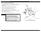
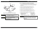
IMPORTANT
The tightening torque for the two CBS screws
(3 ×× 8) is 0.78 - 0.98 Nm (8 - 10 Kgf-cm).
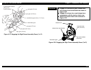
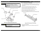
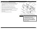
Engage the RD assembly gears as shown in
Figure 4-32.
RD rachet
com bination gear (7 m m , 23 m m )
driven pulley assem bly
spur gear (25 m m )
spur gear (11 m m )
Figure 4-32. Engaging the RD Assembly Gears
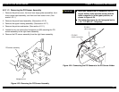
Adjust the platen gap/parallelism and
bidirectional print alignment, and reset the TPE
level. (See Chapter 5.)
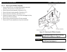
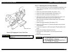
4.2.11.9 Removing the CR Assembly
1.
Remove the printer cover, front and rear edge guide assemblies, front
cover, paper eject assembly, and front and rear tractor units. (See
section 4.2.1.)
2.
Remove the panel board assembly. (See section 4.2.2.)
3.
Remove the upper housing assembly. (See section 4.2.7.)
4.
Remove the printer mechanism. (See section 4.2.11.)
5.
Remove the left frame assembly. (See section 4.2.11.7.)
6.
Remove the RD assembly. (See section 4.2.11.8.)
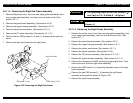
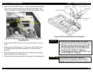
7.
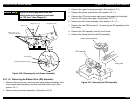
Remove the CR assembly from the front and rear CR guide shafts.
CR assembly
rear CR guide shaft
Figure 4-33. Removing the CR Assembly
8.
Remove the CR assembly.
9.
Remove the timing belt from the two holding slots under the CR
assembly.