


EPSON FX-2180 Service Manual Chapter 4 Disassembly and Assembly
4-14
5.
Disconnect the cables from the following connectors on the main
board assembly.
Table 4-6. Main Board Connectors
Connector
Number
Pins Connector
Color
Connector
Number
Pins Connector
Color
CN4 3 white CN5 3 black
CN6 2 white CN7 4 gray
CN8 18 gray CN9 16 gray
CN10 4 white CN11 5 white
CN12 4 white CN13 4 black
Note: To disconnect the cables from CN10 and CN11, pull up the
connector locks.
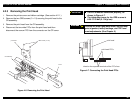
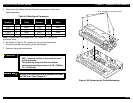
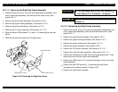
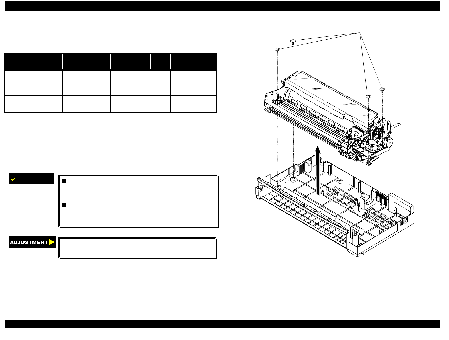
6.
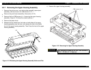
As shown in Figure 4-20, remove the four printer mechanism
mounting screws securing the printer mechanism.
7.
Remove the printer mechanism.
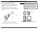
IMPORTANT
When you connect the cables to CN10 and
CN11, align the red line in the cable with pin 1
of the connector.
The tightening torque for the four printer
mechanism mounting screws is 0.78 - 0.98 Nm
(10 - 12 Kgf-cm).
Adjust the bidirectional print alignment and reset
the TPE level. (See Chapter 5.)
printer mechanism mounting screws
Figure 4-20. Removing the Printer Mechanism