


EPSON FX-2180 Service Manual Chapter 4 Disassembly and Assembly
4-28
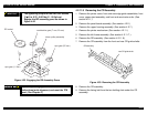
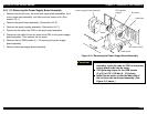
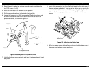
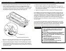
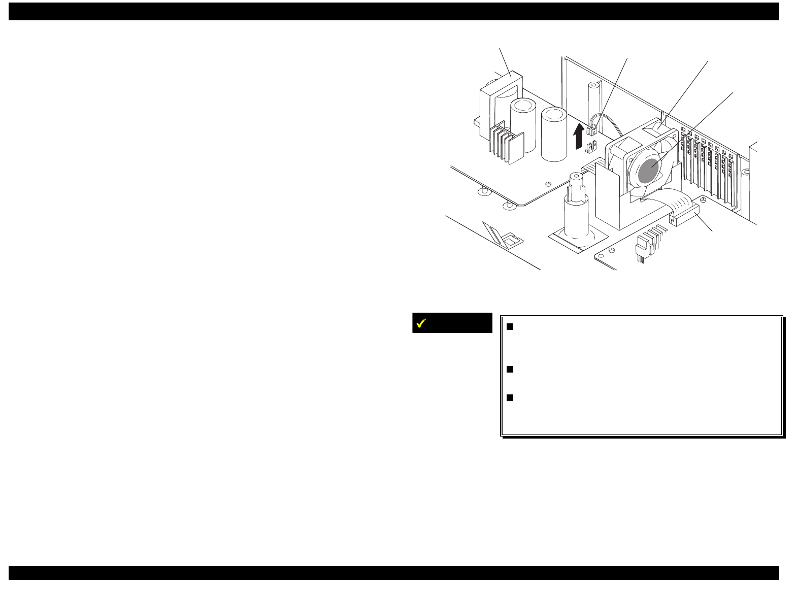
4.2.11.13 Removing the Power Supply Board Assembly
1.
Remove the printer cover, front and rear edge guide assemblies, front
cover, paper eject assembly, and front and rear tractor units. (See
section 4.2.1.)
2.
Remove the panel board assembly. (See section 4.2.2.)
3.
Remove the upper housing assembly. (See section 4.2.7.)
4.
Disconnect the cable from CN3 on the main board assembly.
5.
Disconnect the cable for the fan motor from CN3 on the power supply
board assembly. Then remove the fan motor.
6.
Remove the five CBB screws (3
×
12) securing the power supply
board assembly.
7.
Remove the power supply board assembly.
fan m otor
CN3 (power
supply)
pow er supply board assem bly
label side
m ain board
C N 3 (m ain board)
Figure 4-41. Removing the Power Supply Board Assembly
IMPORTANT
When installing the power supply board
assembly, insert the cable for CN2 on the power
supply board under the fan motor.
The tightening torque for the CBB screws
(3 ×× 12) is 0.78 - 0.98 Nm (8 - 10 Kgf-cm).
Install the fan motor so that the label side of
the fan faces the main board assembly. (See
Figure 4-41 above.)