


EPSON FX-2180 Service Manual Chapter 3 Troubleshooting
3-2
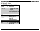
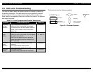
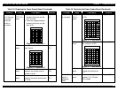
3.2.2 Sensors
Table 3-2. Sensor Test Points
Sensor
Connector
Test Pin
Numbers
Test Method
(Set the meter to DC
voltage.)
Meter Reading
CN4
(HP sensor)
1: HP
2: GND
3: +5 V
Place one lead on pin 1 and
the other lead on pin 2.
Check the resistances while
blocking the two sensor
terminals.
• Open: +5 V
(home position)
• Short: 0 V
(not in home
position)
CN5
(rear PE
sensor)
1: +5 V
2: PE
3: GND
Place one lead on pin 2 and
the other lead on pin 3.
Check the resistances while
toggling the rear PE sensor
lever.
• Open: +5 V
(Paper is loaded.)
• Short: 0 V
(No paper is
loaded.)
CN6
(front PE
sensor)
1: PE
2: GND
Place one lead on pin 1 and
the other lead on pin 2.
Check the resistances while
toggling the front PE sensor
lever.
• Open: +5 V
(Paper is loaded.)
• Short: 0 V
(No paper is
loaded.)
CN7
(TOP sensor)
1: E
2: GND
3: +5 V
4: A
Place one lead on pin 2 and
the other lead on pin 3.
Check the resistances while
inserting and removing paper
between the platen and the
sensor.
• Open: 0 V
(No paper is
loaded.)
• Short: +5 V
(Paper is loaded.)
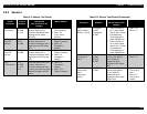
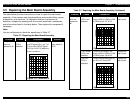
Table 3-2. Sensor Test Points (Continued)
Sensor
Connector
Test Pin
Numbers
Test Method
(Set the meter to DC
voltage.)
Meter Reading
CN12
(paper release
sensors 1 and 2)
1: Release 1
2: GND
3: Release 2
4: GND
1. Place one lead on
pin 1 and the other
lead on pin 2. Check
the resistances
while toggling the
paper release lever.
2. Place one lead on
pin 3 and the other
lead on pin 4. Check
the resistances
while toggling the
paper release lever.
• Open: +5 V
• Short: 0 V
CN13
(PG sensors 1
and 2)
1: PG 1
2: GND
3: PG 2
4: GND
Place one lead on pin 1
and the other lead on
pin 2. Check the
resistances while
toggling the PG sensor
lever.
• Open: +5 V
• Short: 0 V
CN2 on the
control panel
board
(cover open
sensor)
1: COPEN
2: GND
Place one lead on pin 2
and the other lead on
pin 3. Check the
resistances while
toggling the cover open
sensor lever.
• Open: +5 V
(The cover is
open.)
• Short: 0 V
(The cover is
closed.)