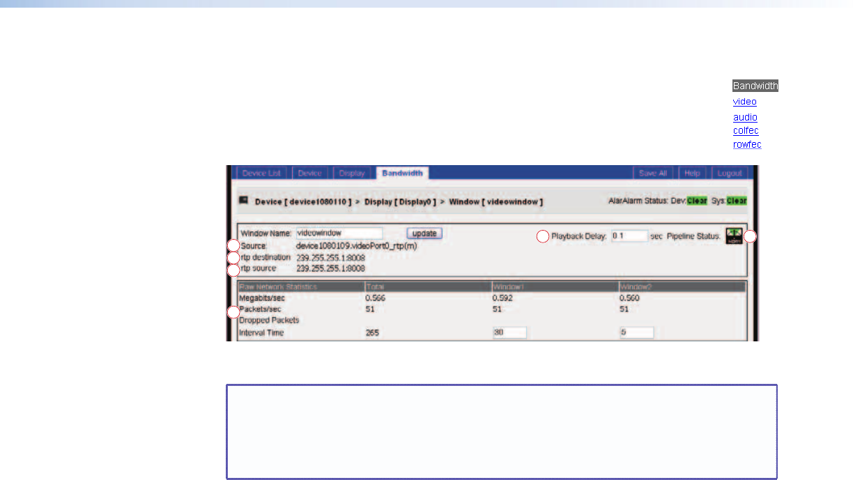
Decoder Bit Rate and Stream Page
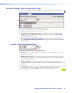
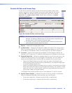
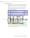
To view the bit rate and statistics for one of the incoming streams (video, audio
and error correction, open the decoder bit rate and streams page for that stream
(see figure 38) on the decoder display and configuration page. Click the desire
Bandwidth link, video, audio, colfec (column error correction), or rowfec
(row error correction).
6
4 5
1
2
3
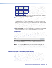
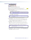
Figure 38. Decoder Bit Rate and Stream Page
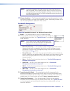
NOTES: • The bit rate statistics reported on this page apply to the stream type you
selected. This display is different from the bit rate statistics reported by the
encoder, which is for the total of all stream types.
• This section is specific to the video data stream. Note that the scheme for
audio and error correction data is the same.
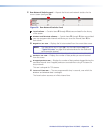
a
Source: — Reports the currently select stream.
b
rtp destination — Reports the IP destination address and port for the current stream.
When connecting using RTP this is either a multicast group address or, for RTP unicast,
the IP address of the decoder. When connecting using TCP, this field is displays 0.
c
rtp source — Reports the multicast group address to which reception statistics are
reported. In RTP unicast and TCP modes this field reports the IP address of the encoder.
d
Playback Delay field — Defines the playback delay, the sum of the transit time in the
network and the time spent in the input buffer of the decoder. You can modify this
setting. Use the PIpeline Status indicator (
e
) as a guideline for the correct value.
• Setting the Playback Delay to too small a value can result in the decoder input
buffer emptying faster than data arrives (underflowing). The playback image jumps
as network loading changes occur.
• Setting the Playback Delay to too large a value can result in the decoder input buffer
filling more quickly than data can be processed (overflowing). The increase in image
latency can result in an internal buffer overflow on high bandwidth data streams, a
jumpy screen update, and screen flashing.
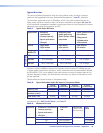
The Playback Delay setting should be set to a value between 0.1 and 0.2 seconds.
e
Pipeline Status indicator — Indicates the status of the input buffer in the decoder.
Adjust the Playback Delay (
d
) so that the meter sits at the mid point.
• If the meter swings left, it indicates that the buffer is underflowing.
• If the meter swings right, it indicates that the buffer is overflowing.
VN-Matrix 325 Serial Digital Over IP CODEC • Operation 49


