


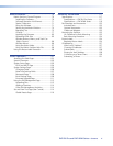
DXP DVI Pro and DXP HDMI Series • Installation 8
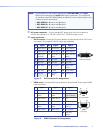
NOTE: LockIt
®
cable lacing brackets, one for each HDMI input and output
connector, are provided with the DXP HDMI. These brackets can be
used to secure the HDMI cables to the DXP connectors to reduce
stress on the HDMI connectors and prevent signal loss due to loose
cable connections.
For information on attaching the LockIt brackets, see the LockIt HDMI
Lacing Bracket Installation Guide card, available on the Extron website
at www.extron.com.
c
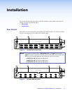
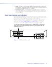
Output connectors —
• DVI Pro series: Connect DVI output devices to these female 29-pin DVI-I output
connectors.
• HDMI series: Connect HDMI output devices to these female 19-pin type A HDMI
output connectors.
NOTE: The switchers do not alter the video signal in any way. The signal that is
output by the switcher is in the same format as the input signal.
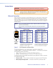
d Ethernet port — If desired, connect the DXP switcher to a computer
or to an Ethernet LAN via this RJ-45 connector. You can use a computer
to control the networked switcher with SIS commands from a remote
location. You can also control the switcher from a PC that is either running
the Matrix Switchers Control Program or via the HTML pages that are pre-loaded on
the switcher (see “Ethernet Connection” on the next page).
Ethernet connection indicators — The Link and Act LEDs indicate the status of
the Ethernet connection. The green Link LED indicates that the switcher is properly
connected to an Ethernet LAN. This LED should light steadily. The amber Act (Activity)
LED indicates transmission of data packets on the RJ-45 connector. This LED should
flicker as the switcher communicates.
e Reset LED — When the unit is being reset, this LED blinks the appropriate number of
times to indicate the level of reset that has been performed.
f Reset button — This recessed button initiates four levels (modes) of reset on the
DXP switcher. To initiate the different reset levels, use a pointed object such as a
small Philips screwdriver or a stylus to press and hold the button while the switcher
is running or while it is being powered up (see “Resetting” on page 38 for more
information).
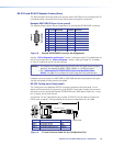
g
Remote RS232/RS422 connector — Connect a host device, such as a computer,
touch panel control, or RS-232 capable PDA to the switcher via this 9-pin D
connector for serial RS-232 and RS-422 control (see “RS-232 and RS-422 Remote
Connections” on page 10).
ACT
LINK
ETHERNET