


DXP DVI Pro and DXP HDMI Series • Operation 18
Powering On
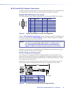
Apply power by connecting the provided IEC power cord to the rear panel IEC connector
and to an AC source. The switcher performs a self-test that flashes the front panel
button indicators red, green, and amber and then turns them off. An error-free power-up
self-test sequence leaves all I/O and control buttons either unlit or showing background
illumination. The lit or unlit status of the Video and Audio buttons remains the same as it
was when the switcher was previously powered off.
The current conguration, EDID information, and all presets are saved in memory. When
power is applied, the most recent configuration is retrieved. The previous presets remain
intact.
If an error occurs during the self-test, the DXP locks up and does not operate. If this
occurs, call the Extron S3 Sales & Technical Support Hotline (see the rear cover for contact
information in your area).
Creating a Configuration
A configuration consists of one or more inputs, each tied to a set of one or more outputs.
NOTE: While an input can be tied to multiple outputs, an output can be tied to only
one input.
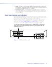
This section contains the steps to follow to create or change a configuration. The following
subsections contain some examples of configurations that can be created on the DXP,
and instructions for setting them up. The illustrations show the DXP 88; however, the
procedures apply to all DXP models.
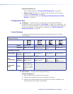
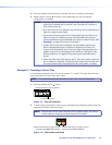
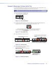
To create a configuration:
1. Press the Esc
>
button to clear any input, output, or control button indicators that
may be lit.
2. Select to configure video, audio, or both by pressing the
Video and Audio buttons (
h
and
i
in figure 10).
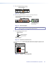
3. Select the desired input and outputs by pressing the input and output buttons
(
a
and
b
in figure 10).
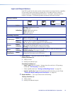
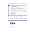
• The input buttons light one of the following colors:
• Amber: Video and audio ties
• Green: Video only ties
• Red: Audio only ties
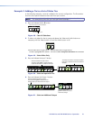
• Output buttons light or blink one of the following colors:
• Amber: Video and audio ties
• Green: Video only ties
• Red: Audio only ties
• To indicate potential ties, output buttons blink in the appropriate color when an
input is selected.
• To indicate current ties, output buttons light steadily in the appropriate color
when an input is selected.
• To clear unwanted outputs, press and release the associated lit output buttons. To
indicate potential unties, output buttons blink the appropriate color when an
output is deselected (muted) but not untied from the input.