


2-3
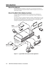
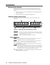
MVX 128 A VGA Matrix Switchers • Installation
PRELIMINARY
Audio connections
By default, the audio ties follow the video ties. Audio breakaway, which can
be activated via the front panel or under RS-232/RS-422 control, allows you to
select from any one of the audio input sources and route it separately from its
corresponding video source. See chapter 3, Operation, chapter 4, Programmer’s
Guide, and chapter 5, Matrix Software for details.
c
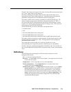
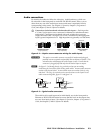
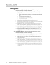
Connections for balanced and unbalanced audio inputs — Each input has
a 3.5 mm, 5-pole captive screw connector for balanced or unbalanced stereo
audio input. Connectors are included with each switcher, but you must
supply the audio cable. See fi gure 2-2 to wire a connector for the appropriate
input type and impedance level. High impedance is generally over 800 ohms.
Unbalanced Input
Tip
Sleeve
Tip
Sleeve
Balanced Input
Tip
Ring
Sleeve (s)
Tip
Ring
Tip
Ring
Sleeve (s)
Tip
Ring
Balanced Input
(high impedance)
(high impedance) (600 ohms)
600 ohms
600 ohms
Figure 2-2 — Captive screw connector wiring for audio inputs
C
The captive screw audio connector can easily be inadvertently plugged
partially into one receptacle and partially into an adjacent receptacle. This
misconnection could damage the audio output circuits. Ensure that the
connector is plugged fully and only into the desired input or output.
N
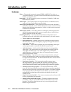
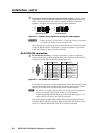
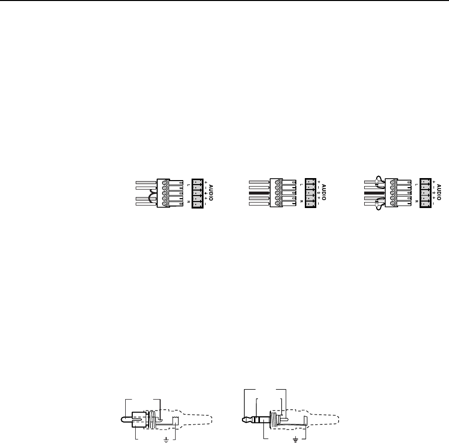
See fi gure 2-3 to identify the tip, ring, and sleeve when you are making
connections for the switcher from existing audio cables. A mono audio connector
consists of the tip and sleeve. A stereo audio connector consists of the tip, ring
and sleeve. The ring, tip, and sleeve wires are also shown on the captive screw
audio connector diagrams, fi gure 2-2 and fi gure 2-4.
Tip (+)
Sleeve ( )
Sleeve ( )
Ring (
-
)
Tip (+)
RCA Connector
3.5 mm Stereo Plug Connector
(balanced)
Figure 2-3 — Typical audio connectors
The audio level for each input can be individually set via the front panel or
Ethernet or RS-232/RS-422 control to ensure that the level on the output does
not vary from input to input. See chapter 3, Operation; chapter 4, Programmer’s
Guide; and chapter 5, Matrix Software for details.