


Operation, cont’d
MVX 128 A VGA Matrix Switchers • Operation
3-24
PRELIMINARY
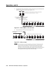
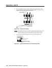
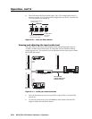
4. Press and release the Enter button (fi gure 3-40). The confi guration stored in
memory location 13 is now the current confi guration and can be viewed in the
View-Only mode (see example 4).
ENTER PRESET VIEW ESC
CONTROL
The Enter and Preset LEDs
return to the unlit state.
Press the Enter button to
recall the preset.
All input LEDs
return to the
unlit state.
Figure 3-40 — Press the Enter button
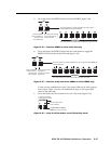
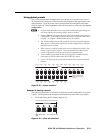
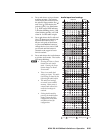
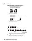
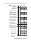
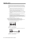
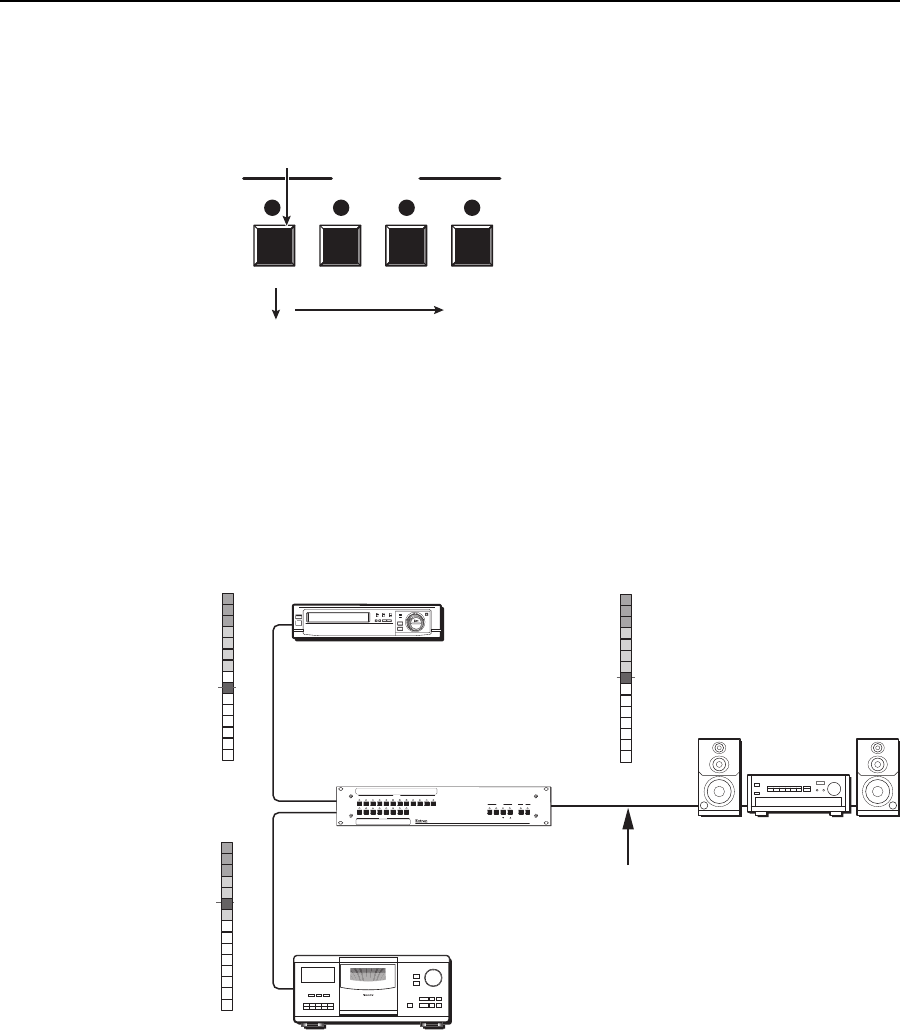
Viewing and adjusting the input audio level
The audio level of each input can be displayed and adjusted through a range of
-18 dB to +24 dB to ensure that there is no noticeable volume difference among
sources (fi gure 3-41). The audio level can be adjusted from the front panel or under
RS-232/RS-422 control.
Audio
Inputs
Audio
Inputs
VCR
No noticeable
volume differences
between sources
Audio System
CD Jukebox
MVX 128 A
0
-3
-6
-9
-12
-15
Low Audio
Output Level
+4
+1
-2
-5
-8
-12
-18
-21
-15
-18
3 +7
6 +10
9 +13
12 +16
15 +19
18 +21
21 +24
VU dBu
0
-3
-6
-9
-12
-15
High Audio
Output Level
+4
+1
-2
-5
-8
-12
-18
-21
-15
-18
3 +7
6 +10
9 +13
12 +16
15 +19
18 +21
21 +24
VU dBu
0
-3
-6
-9
-12
-15
Output
Level
+4
+1
-2
-5
-8
-12
-18
-21
-15
-18
3 +7
6 +10
9 +13
12 +16
15 +19
18 +21
21 +24
VU dBu
1 2 3 4 5 6 7 8
1 2 3 4 5 6 7 8
9 10 11 12
INPUTS
OUTPUTS
AUDIO
VIDEO
I/O
CONTROL
ENTER
PRESET
VIEW
ESC
MVX SERIES
VGA MATRIX SWITCHER
WITH
ADSP
TM
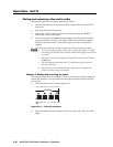
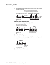
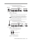
Figure 3-41 — Audio gain and attenuation
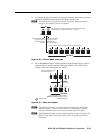
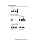
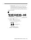
1. Press the Esc button to clear any input LEDs, output LEDs, or control LEDs
that are lit.
2. To enter the Audio mode, press and hold the Audio button until the LED
begins to blink, then release the button.