


2-5
PVS 305SA Switcher • Installation
PRELIMINARY
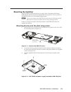
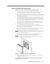
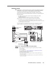
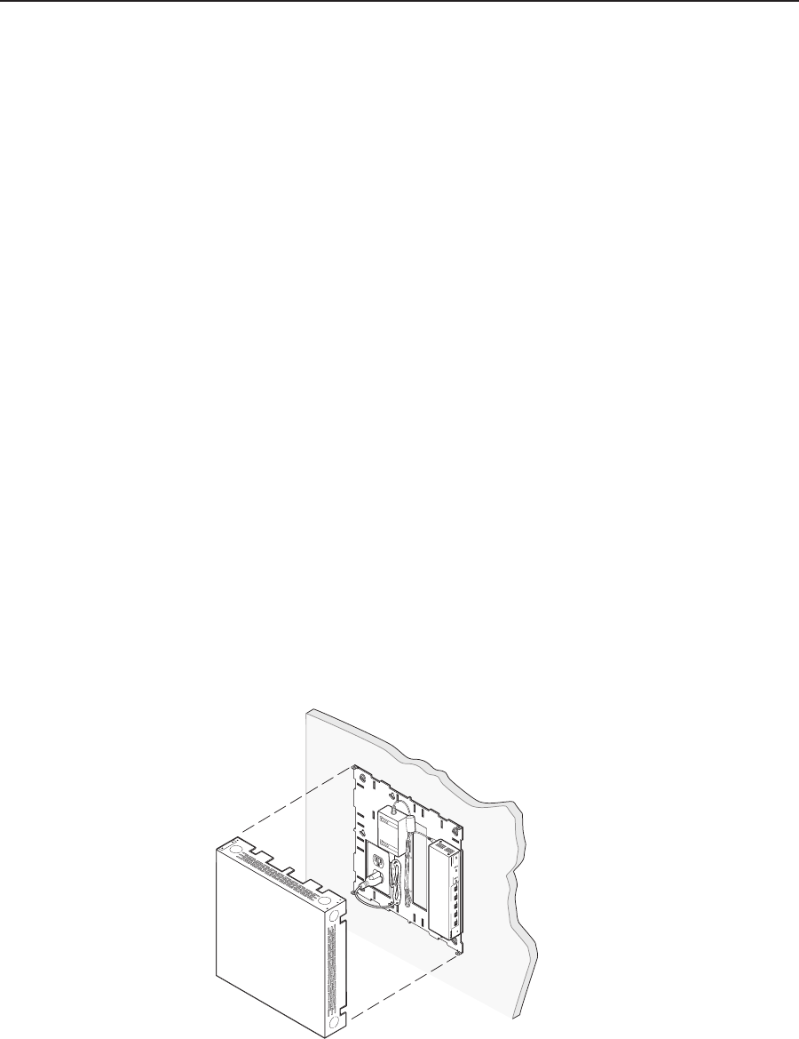
Wall mounting the PoleVault switcher
Using the Extron WMK 100 Wall Mounting Kit, the PoleVault switcher can be
mounted on a wall near a flat screen display or short throw projector.
1
. Following the instructions supplied with the WMK 100, prepare the wall and
temporarily mount the base plate on the wall at the desired location.
2
. Run the signal cables from the PoleVault input wallplates, control device, and
the speakers to the WMK 100 location. Cables can be routed behind the walls,
or through a surface raceway.
3
. Remove the WMK 100 base plate from the wall, and with the switcher’s rear
ports facing the cable access hole, align the two corner holes in the base of the
switcher with the two outermost device mounting holes in the WMK 100 base
plate. Secure with the supplied 440 x ¼ inch screws.
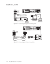
4
. Use the supplied hook-and-loop straps to attach the power supply above the
electrical outlet cutout. Rout the cables to the electrical outlet and switcher.
5
. Re-attach the plate to the wall and secure firmly.
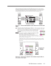
6. Connect the cables from the PoleVault transmitters, control device
(MediaLink Controller), speakers, and optional accessories (VoiceLift, Page
Sensor Kit) to the rear ports of the switcher.
7
. Run VGA and composite video ouput cables from the switcher to the output
display device through the wall or, where fitted, the raceway.
8
. Connect the power supply to the switcher and plug it in to the outlet.
N
If the electrical outlet is outside the WMK, pass the IEC power cable out through
one of the raceway knockouts.
9. After completion of cabling, place the cover over the installed plate, and
secure at each corner with the provided 6-32 button head screws.
N
Ensure any cables exiting the box (e.g., to display device and external electrical
outlet) pass through a raceway knockout.
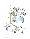
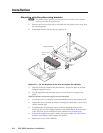
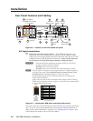
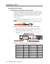
PVS 305SA
POLEVAULT SWITCHER
INPUT SELECTION
1
2
PEAK
NORMAL
SIGNAL
CONFIG
3 4
5
AUX AUDIO
AUDIO LEVEL ADJUST
PAGING
SENSOR
SENSITIVITY
VOICELIFT
MIC
PEAK
NORMAL
SIGNAL
INPUT
Figure 2-4 — Cable the device and attach the cover
10. Switch on the display device, control device, signal sources and adjust and
configure the system as needed.
For full PoleVault System configuration and setup details, refer to the
PoleVault
System Installation Manual, or the MLC 104 Plus Series Reference Manual, both
available online at www.extron.com.