


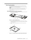

2-11
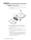
PVS 305SA Switcher • Installation
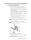
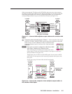
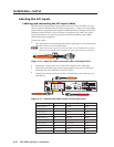
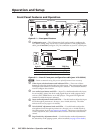
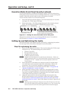
Speaker output
j
Amplified audio out — Connect one speaker to each
channel marked “L” and “R” (left and right) using the
supplied black 4-pin 5 mm connector. Wire the red cable to
positive and the black cable to negative. Each channel
is rated for 25 W at 2, 4, or 8 ohm loads.
If using more than one speaker per channel, connect them in parallel.
Refer to appendix B, “Speaker Configuration” section, for details on speaker
configuration.
C
Do not tie both L and R outputs to each other and/or to ground
as it
may short the outputs and damage the amplifier.
N
The speaker setup covers two individual speakers of 8 ohm impedance or two
pairs of speakers in parallel, where each channel drives a maximum output load
of 2 ohms.
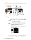
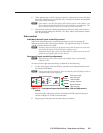
Line out audio output
k
Line out audio port — This port is used for connecting an Extron
external amplifier, recording, podcasting, or assisted listening
devices. It can be configured via RS-232 for fixed or variable
audio output (default is variable). It can be wired for balanced or unbalanced
signals. See appendix B for wiring details.
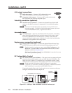
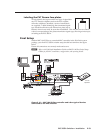
Power supply connector
l
DC power connector — When all other cables have been connected, plug
the round power jack from the 12 VDC
power source
into this connector to
power the switcher, the PVT wallplates, the MediaLink controller and, where
installed, the VoiceLift receiver
. One of the five front panel input button LED
is lit when the PVS 305SA is receiving power.
N
Use only the supplied 12 V, 5 A power supply for this switcher.
The PVS 305SA power supply can support a typical system: for example,
a PVS 305SA, 4 PVT Wallplates, 2 or 4 speakers, an MLC 104 IP Plus with an
IRCM DV+, and a VoiceLift Microphone system.
If an SCP 104 is used in the system, the MLC 104 IP Plus MUST have its own
power supply.
L R
2/4/8 Ohms
AMPLIFIED OUTPUTS
L R
LINE OUT