


3-3
PVS 305SA Switcher • Operation and Setup
PRELIMINARY
Front panel operation
N
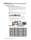
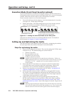
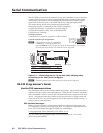
See the front panel image (figure 3-1) for the location of input buttons, adjustment
knobs, LEDs, and configuration port.
• To change inputs, select an input button, 1 through 4 (video and audio),
or 5 (audio only).
• To adjust audio input levels, rotate the Input adjustment knob through 43
positions in 1 dB steps (-18 to +24 dB, default 0).
• To adjust VoiceLift microphone levels, rotate the MIC adjustment knob through
43 positions in 1dB steps (-18 to +24 dB, default 0).
N
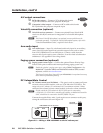
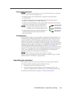
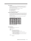
Front panel LEDs indicate input and mic levels
(see image at right). On initial switcher power-up
the amplifier level is automatically adjusted to 50%.
• To adjust paging sensitivity, rotate the Paging knob
clockwise to increase and counter-clockwise to
decrease sensitivity.
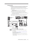
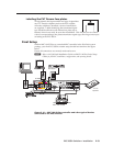
Configuration
The PVS 305SA switcher can be controlled by a MediaLink Controller (MLC) or by
an RS-232 device acting through the MLC. Alternatively, the switcher can be set
up and controlled via a host computer or other device (such as a control system)
attached to the switcher’s rear panel RS-232/MLC/IR port. The control device
(host) can use either the Extron Simple Instruction Set (SIS
™
) commands, the Global
Configurator (GC) program for Windows, or the MediaLink Switchers (MLS) and
PoleVault Switchers (PVS) control software
, available at www.extron.com.
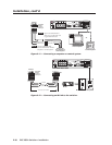
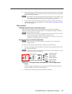
Firmware updates can be made via the front panel configuration port before installation
(connect
a 2.5 mm configuration cable, part # 70-335-01, to the serial port on the front
panel). After installation they can be made through a IP link via the MediaLink
Controller connected to the PVS 305SA’s rear RS-232 port.
N
R
efer to chapter 4 for a full list of the relevant SIS commands.
Inputs 3 and 4 can be configured for signal type (RGB or composite video) via RS-232
and SIS commands. The default is composite video.
Resetting the Switcher
The switcher can be reset to the factory defaults via the front panel or RS-232.
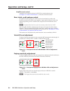
To reset the switcher via the front panel, follow these steps.
1
. Unplug the switcher from the power source.
2. Press and hold input selection button 1 while reapplying power to the
switcher. All input selection LEDs blink for 1 second during switcher reset.
For details on RS-232 control, see chapter 4, “Serial Communication”.
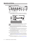
PEAK
NORMAL
SIGNAL
Signal threshold;
raise input gain.
Level has been
properly adjusted.
Level set too high,
lower input gain.