


2-7
PVS 305SA Switcher • Installation
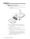
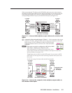
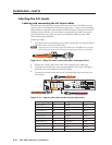
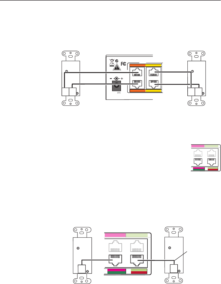
When connecting the TP cables to the PVS 305SA, take care not to cross-connect
the cables; connect input cable 1A to the RJ-45 port labeled 1A, and input cable 1B
to the RJ-45 port labeled 1B. Likewise, connect input cables 2A, 3A, or 4A to its
corresponding numbered A port, and cable B to its B port (see figure 2-7).
PVT RGB D
Input #2
RGB B
OUT
Rear Panel
RGB A
OUT
I
N
P
U
T
S
RGB
RGB Input Connectors on
Rear Panel of PVS 305SA
Cable from
PVT Output A
Cable from
PVT Output B
Cable from
PVT Output A
Cable from
PVT Output B
1A
2A
1B
2B
N15779
POWER
12V
5A MAX
PVT RGB D
Input #1
RGB B
OUT
Rear Panel
RGB A
OUT
Figure 2-7 — Connect RGB wallplate output cables to the switcher RGB
inputs.
b
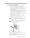
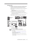
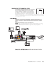
Composite video and audio inputs (”Video”) — Each composite video input
needs one TP cable. Using TP cable, connect up to two composite video and
audio sources via PVT wallplates to these two RJ-45 female
connectors labeled 3 and 4; each one is for video and audio
combined.
N
These ports can also be configured via RS-232 for RGB
video input. Default is for composite video.
When connecting the TP cables to the switcher, take care to
connect input 3’s cable to the RJ-45 port labeled 3, and input 4’s cable to the
RJ-45 port labeled 4 (see figure 2-8).
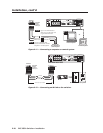
Though these ports can also be used for RGB signals, do not connect an RGB
cable (cable A) to the top ports when connecting composite video inputs to the
lower ports.
See the note on page 2-6 about cables and cable termination.
PVT CV D
Input #3
PVT CV D
Input #4
Rear Panel
Rear Panel
Composite Video Input
Connectors on
Rear Panel of PVS 305SA
Composite Video
Cable from
PVT Output
3A RGB 4A RGB
RGB
VIDEO
RGB
VIDEO
3B 4B
Figure 2-8 — Connect the composite video wallplate output cables to
the switcher video inputs.
3A RGB 4A RGB
RGB
VIDEO
RGB
VIDEO
3B 4B