


3-5
PVS 305SA Switcher • Operation and Setup
PRELIMINARY
6. When adjustments to all five inputs’ sensitivity settings have been made, then
adjust the amplifier level (via RS-232 only). Increase or decrease the amplifier
level very slowly, if needed.
N
If the volume is at 100% through the MLC and the output on the speakers is too
loud, reducing the amp level via RS-232 control software is recommended. This
ensures that the volume will not be too loud, even when set at 100%.
7. Fine tune the audio by making adjustments to the bass, treble, and loudness
until the desired settings are reached. See “Bass, treble, and loudness control”
later in this chapter.
Gain control
Individual channel input sensitivity control
Individual channel input gain control adjustments are made by rotating the
adjustment knob for the selected input button. The adjustment range is -18 dB to
+24 dB, with the default set at 0 dB.
N
Adjusting input sensitivity for all inputs ensures that all inputs are at the same
level and at the highest level possible before clipping occurs.
Individual channel input gain levels either adds to or subtracts from the overall
(global) power amplifier gain level per channel.
Front panel input sensitivity adjustment
N
Upon initial power up of the switcher, the amplifier level is automatically
adjusted to 50%.
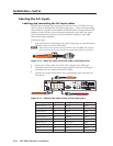
To make sure the right input sensitivity is attained, do the following:
1
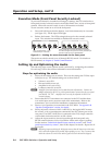
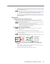
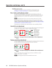
. For the active input (with the LED lit), rotate the level adjustment knob until
the Normal LED blinks.
N
Having the audio level beyond the point at which the peak LED flashes results in
a distorted output signal (clipping).
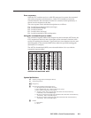
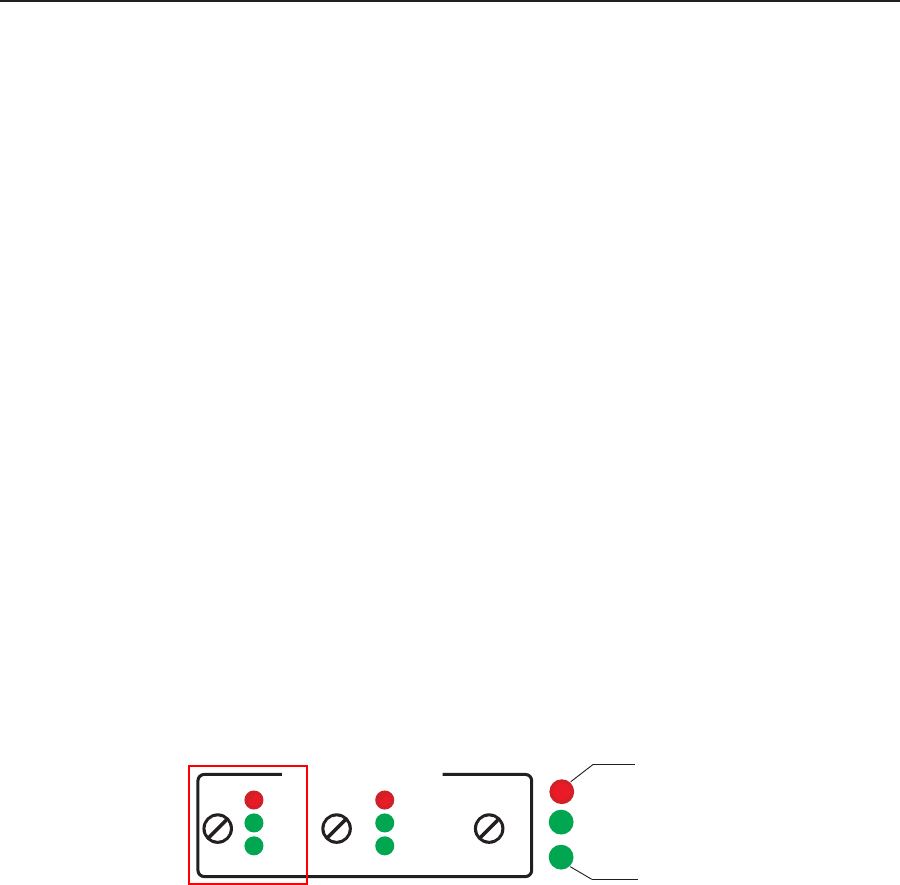
PEAK
NORMAL
SIGNAL
AUDIO LEVEL ADJUST
PAGING
SENSOR
SENSITIVITY
VOICELIFT
MIC
PEAK
NORMAL
SIGNAL
INPUT
PEAK
NORMAL
SIGNAL
Signal threshold;
raise input gain.
Level has been
properly adjusted.
Level set too high,
lower input gain.
Figure 3-4 — Front panel Input audio Min/Max LED and adjustment
knobs
Individual gain adjustment can also be made by RS-232 control software as
shown in chapter 4, “Serial Communication”.
4
. Repeat steps 1 through 3 for the other inputs as desired.