


PVS 305SA Switcher • Installation
2-6
Installation
PRELIMINARY
Rear Panel Features and Cabling
L R
L R
L R
AUX AUDIO
INPUT 5
LINE OUT
VOICELIFT
RECEIVER
PAGING
SENSOR
DO NOT
GROUND
OR SHORT
SPEAKER
OUTPUTS
1B RGB
1A RGB
2B RGB
2A RGB
3B RGB
/VIDEO
4B RGB
/VIDEO
3A RGB 4A RGB
I
N
P
U
T
S
RS-232 MLC/IR
2/4/8
Ohms
CLASS 2 WIRING
AMPLIFIED AUDIO OUT
VOL/MUTE
Tx RxIR 12V
10V 50mA
POWER
US
LISTED
17TT
AUDIO/VIDEO
APPARATUS
®
RGB
VIDEO
OUTPUTS
CONTROL
N15779
12V
5A MAX
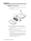
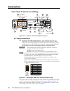
PVT RGB D
PVT RGB D Plus Inputs
(1-4, A and B)
Power Supply
Connector
PVT CV D Inputs
(3 and 4)
RGB
Output
Video
Output
Speaker
Output
Aux Audio
Input
MLC Control
Port
VoiceLift
Receiver Port
Lineout
Output
Volume/Mute
Control Port
Paging Sensor
Port
2A RGB
1A RGB
1B RGB
2B RGB
4A RGB
3A RGB
RGB
VIDEO
6
8
7
1
10
5
9
3
4
12
2
11
3B
RGB
VIDEO
4B
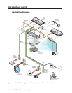
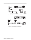
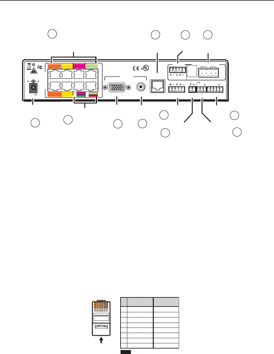
Figure 2-5 — Features of the PVS 305SA rear panel
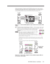
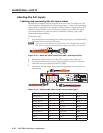
A/V input connections
a
RGB video and audio inputs (“RGB”) — Each RGB input (inputs 1 to 4)
requires the use of two twisted pair (TP) cables, A and B. Using TP cables,
connect up to four high resolution computer video and audio sources via PVT
wallplates to these eight RJ-45 female connectors. Inputs 3 and 4 need to be
set via software to accept RGB signals (default is composite video).
C
The PoleVault
signal transmission method is specific for PVS 305SA
switchers working with PVT wallplates.
DO NOT connect to an MTP system.
DO NOT connect to an Ethernet/LAN or data transmission system.
N
The PVS 305SA is capable of receiving signals from PVT wallplates located up
to 100 feet (30m) away. The optimum distance is between 50 and 75 feet
(15 and 22 meters). Minimum distance is 15 feet (4.6 meters).
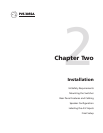
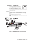
The RGB cables supplied with the PoleVault system are terminated to the
TIA/EIA T568A standard.
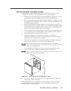
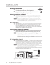
If other cables are used the RJ-45 termination must comply with the T568A or
T568B wiring standards (as shown in figure 2-6), and the same standard MUST
be used at both ends of the cables.
12345678
RJ-45
Connector
Insert Twisted
Pair Wires
Pins:
Pin
1
2
3
4
5
6
7
8
Wire color
White-green
Green
White-orange
Blue
White-blue
Orange
White-brown
Brown
Wire color
T568A T568B
White-orange
Orange
White-green
Blue
White-blue
Green
White-brown
Brown
NOTE If you are using Enhanced
Skew-Free™ A/V cable, use the
TIA/EIA T568A standard only.
Figure 2-6 — Twisted pair RGB video and audio cable wiring
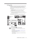
The ports on the rear of the PVS 305SA are color coded for input number and signal
type. To ensure correct cable identification and connection during installation, a
sheet of color coded cable labels is supplied. See “Labeling the A/V Inputs”, later
in this chapter, for details on how to use these labels.