


2-9
PVS 305SA Switcher • Installation
Switcher control
i
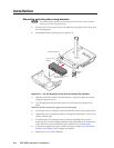
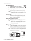
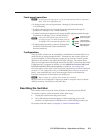
Control port — The PVS switcher can be controlled via an RS -232 connection
directly from a host computer, a control system, or a MediaLink Controller.
For IR remote control connect an Extron IR Link to this port. RS-232
connection can be used to configure the PVS switcher.
Connect a cable
between this port and an Extron MediaLink Controller or an optional IR Link
IR signal repeater.
• The MLC provides remote control of input switching and volume.
The RS-232 protocol is
• 9600 baud • 8-bit • 1 stop bit • no parity • no flow control.
Refer to the
MLC 104 IP Plus Series Reference Manual for full details.
• The IR Link accepts modulated IR signals from a remote control (for
example, the Extron IR 452 remote) enabling the remote control to be used
for selecting the switcher inputs.
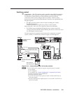
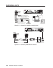
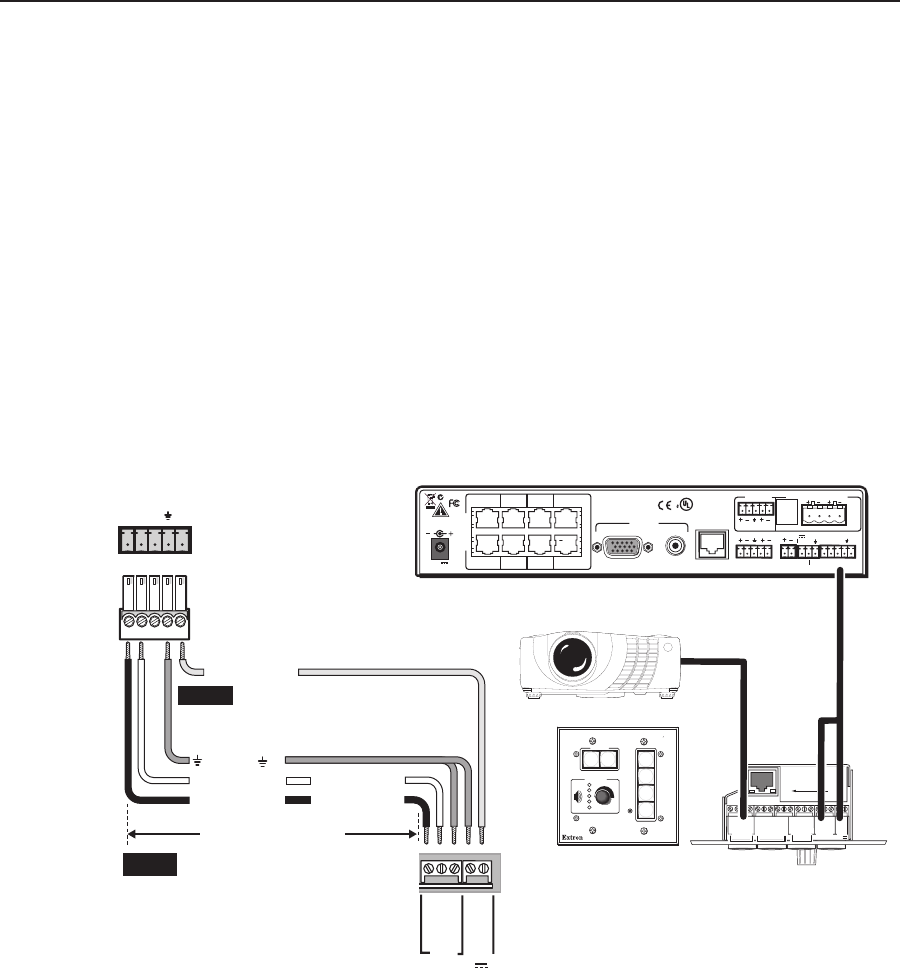
Wire the captive screw connector and connect it to a computer or control
system, an MLC, or an IR Link, as shown in figures 2-10 through 2-12.
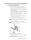
MLC 104 IP Plus front and side panels
2
3
GR OUN D
1
IR IN
GR OUN D
IR OU T
CM
SC P
GR OUN D
GR OUN D
Tx
Rx
DISPLAY
RS-232/IR
LAN
PRESS TAB WITH
TWEEKER TO REMOVE
A B
MLS PWR
RS-232 12V
DIGITAL
I/O
A B C D E
COMM LINK
+V OU T
GR OUN D
Tx
Rx
+1 2V IN
CONFIG
DISPLAY
VOLUME
MLC 104 IP PLUS
ON
VCR
DVD
PC
OFF
1
2
3
4
CONTROL
A B C
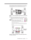
PVS 305SA Switcher's
rear panel
Control port
NOTE You must connect a ground
wire between the MLC and the
switcher.
MLC 104 IP Plus
MLS and power ports
NOTE If you use cable that has a drain
wire, tie the drain wire to ground
at both ends.
D
E
Tx Rx IR
+
12 V
RS-232 12V
MLS PWR
A B
Rx
Tx
GROUND
GROUND
+12V IN
Ground ( )
Transmit (Tx)
B
Receive (Rx)
A
Transmit (Tx)
Receive (Rx)
B
A
+12 VDC input
50 feet (38 m) maximum
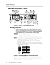
PVS 305SA Rear Panel
L R
L R
L R
AUX AUDIO
INPUT 5
LINE OUT
VOICELIFT
RECEIVER
PAGING
SENSOR
DO NOT
GROUND
OR SHORT
SPEAKER
OUTPUTS
1B RGB
1A RGB
2B RGB
2A RGB
RGB
VIDEO
RGB
VIDEO
3A RGB 4A RGB
I
N
P
U
T
S
RS-232 MLC/IR
2/4/8
Ohms
CLASS 2 WIRING
AMPLIFIED AUDIO OUT
VOL/MUTE
Tx Rx IR 12V
10V 50mA
POWER
US
LISTED
17TT
AUDIO/VIDEO
APPARATUS
®
RGB
VIDEO
OUTPUTS
CONTROL
N15779
12V
5A MAX
RS-232
RS-232
and power
Projector
4B
3B
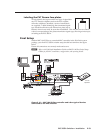
Figure 2-10 — Connecting an MLC 104 to the switcher
N
The PVS 305SA power supply can support a typical system, for example:
• a PVS 305SA
• 4 PVT Wallplates
• 2 or 4 speakers (see “Speaker Configuration” in appendix B for details)
• an MLC 104 IP Plus with an IRCM DV+
• VoiceLift microphone system
• If an SCP 104 is used in the system, the MLC 104 Plus MUST have its
own power supply.
• The PVS 305SA provides sufficient power to run an MLC 104 IP Plus or
MLC 226 IP model.