


2-13
PVS 305SA Switcher • Installation
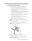
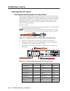
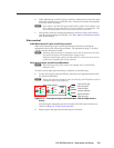
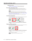
Labeling the PVT Decora face plates
To help identify the input number and type of signal that
any PVT Decora wallplate sends to the PVS switcher
when the wallplate is installed, a series of small labels
are supplied. A label identifying the transmitted signal
type should be affixed to each Decora face plate (top or
bottom) where it can easily be seen after installation. This aids the user to connect
a device corresponding to the plate transmission signal type, allowing correct input
switching at the PVS 305SA.
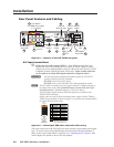
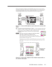
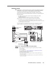
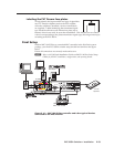
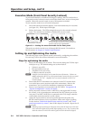
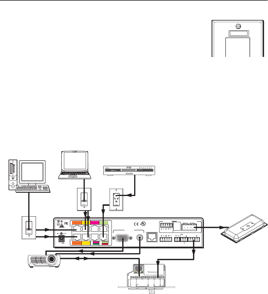
Final Setup
With an MLC 104 IP Plus as a standard MLC controller in the PoleVault system
package, your final PVS 305SA switcher setup should look similar to the figure
below.
Ensure all connections are correctly made and secure.
N
Refer to the PoleVault Installation Guide and MLC 104 Plus Series Setup
Guide
for full MLC installation, configuration, and operating details.
FF 120
Speakers
L R
L R
L R
AUX AUDIO
INPUT 5
LINE OUT
VOICELIFT
RECEIVER
PAGING
SENSOR
DO NOT
GROUND
OR SHORT
SPEAKER
OUTPUTS
1B RGB
1A RGB
2B RGB
2A RGB
3B RGB
/VIDEO
4B RGB
/VIDEO
3A RGB 4A RGB
I
N
P
U
T
S
RS-232 MLC/IR
2/4/8
Ohms
CLASS 2 WIRING
AMPLIFIED AUDIO OUT
VOL/MUTE
Tx Rx IR 12V
10V 50mA
POWER
US
LISTED
17TT
AUDIO/VIDEO
APPARATUS
®
RGB
VIDEO
OUTPUTS
CONTROL
N15779
12V
5A MAX
2A RGB
1A RGB
1B RGB
2B RGB
4A RGB
3A RGB
RGB
VIDEO
3B
RGB
VIDEO
4B
DVD Player
PVT RGB D
PVT RGB D
COMPUTER IN
AUDIO IN
PVT CV D
AUDIO IN
L
R
VIDEO IN
IR OUT
S G
MLC 104 IP Plus
RS-232
RS-232
Projector
+V
G
SC P
+1 2V OUT
PW R S NS
GR OUN D
GR OUN D
GR OUN D
GR OUN D
GR OUN D
Tx
Rx
HOST/
CONFIG
LAN
PRESS TAB WITH
TWEEKER TO REMOVE
A B
A B E
SCP
COMM
MLS
RS-232
PWR
12V
PROJECTOR
RS-232/IR
Tx /IR
Rx
Tx
Rx
+1 2V IN
Laptop
PC
COMPUTER IN
AUDIO IN
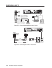
Figure 2-14 — MLC 104 IP Plus controller and other typical devices
connected to the PVS switcher.
RGB IN #1