


Installation, cont’d
PVS 305SA Switcher • Installation
2-8
PRELIMINARY
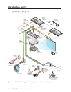
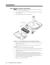
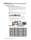
A/V output connections
c
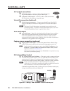
RGB video output — Connect a VGA cable to this female
15-pin HD connector and to the projector RGB input.
d
Composite (video) output — Connect an RCA cable to this female
RCA jack and to the projector composite input.
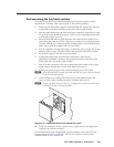
VoiceLift connection (optional)
e
VoiceLift receiver connector — Connect an optional Extron VoiceLift IR
receiver to this RJ-45 connector for integration of a VoiceLift Microphone
system.
N
The Extron VoiceLift Microphone is an optional accessory which must be
purchased separately. To install the VoiceLift Microphone system, refer to the
“VoiceLift Installation Guide”, supplied with the device.
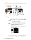
Aux audio input
f
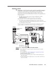
Aux audio input — Input 5 is a dedicated audio only input for an auxiliary,
stereo, line-level audio signal from an audio output source such as audio
from a DVI/HDMI device or an MP3 player. Connect a cable from the
source to this 5-pole captive screw connector. It can be wired as balanced or
unbalanced. See appendix B for wiring details.
Paging sensor connection (optional)
g
Paging system sensor input — Connect the optional Extron Priority Page
Sensor to this port to enable audio interrupts during paging system use.
N
Enable the switcher’s paging sensor port, using Global Configurator or the
MediaLink
®
Switchers (MLS) and PoleVault Switchers (PVS) control
software
, available at www.extron.com.
The Extron Priority Page Sensor Kit (part #70-619-01) is an optional accessory
which must be purchased separately.
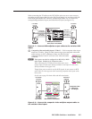
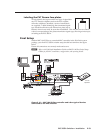
DC Volume/Mute Control
h
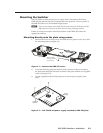
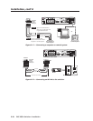
DC Volume control port (Vol/Mute) — This port is used to connect an Extron
external volume control module, such as a VCM 100 to the PVS 305SA. The
range is 0 to 10 V, where 0 V is mute and 10 V is maximum volume. When
connected, the external volume control module is the sole volume controller.
N
Do not control the PVS volume via RS-232 if this port is connected to
a VCM 100. If a VCM 100 is controlling the volume, an MediaLink Controller
(MLC) should not be connected to the MLC/IR/RS-232 port.
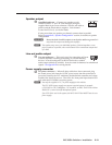
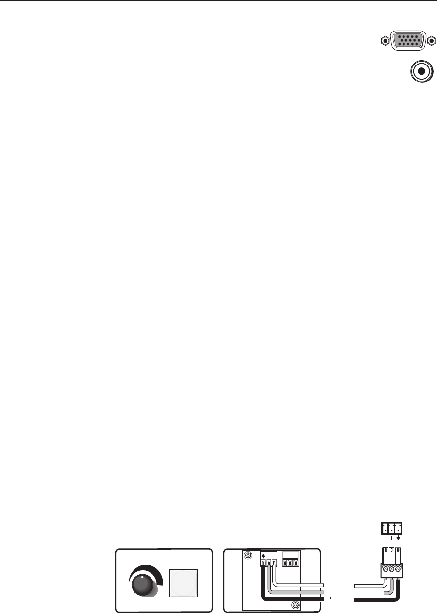
Connect the supplied blue, male, 3-pole captive screw connector to this port,
wiring the connector as shown in figure 2-9.
VOL/
MUTE
10V
MUTE
VOLUME
VCM 100 MAAP
DC VOL
VOL/MUTE
10 V
10 V
Ground
VCM 100 MAAP front and rear panels
PVS 305SA
DC Volume port
Variable voltage or mute
Figure 2-9 — Wiring a VCM 100 MAAP to the DC volume port