


Appendix B, cont’d
PVS 305SA Switcher • Appendix B
B-4
L R
L R
L R
AUX AUDIO
INPUT 5
LINE OUT
VOICELIFT
RECEIVER
PAGING
SENSOR
DO NOT
GROUND
OR SHORT
SPEAKER
OUTPUTS
1B RGB
1A RGB
2B RGB
2A RGB
3B RGB
/VIDEO
4B RGB
/VIDEO
3A RGB 4A RGB
I
N
P
U
T
S
RS-232 MLC/IR
2/4/8
Ohms
CLASS 2 WIRING
AMPLIFIED AUDIO OUT
VOL/MUTE
Tx RxIR 12V
10V 50mA
POWER
US
LISTED
17TT
AUDIO/VIDEO
APPARATUS
®
RGB
VIDEO
OUTPUTS
CONTROL
N15779
12V
5A MAX
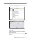
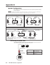
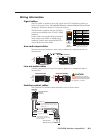
Connect this port to the MLS port on the MLC 104 IP Plus.
The switcher powers the MLC 104 IP Plus.
Insert the round plug from
the supplied 12 VDC, 5 A
power supply.
Power
Connect RGB and composite
video outputs to a display device.
N
Optimal cable distance is between 50 and 75 feet (15 and 22 m),
minimum distance is 15 feet (5 m).
CAT 5/5e/6 rated.
Inputs 3 and 4 can be configured via RS-232 for either RGB
or composite video (default).
C Do NOT connect this device to a computer data or telecommunications network.
Do NOT short output terminals to ground as it may damage the switcher.
Switcher Control
Protocol: 9600 baud, 8 bit,1 stop bit, no parity, no flow control
Connect one speaker
(left and right)
to each port
(red to positive, black to negative).
If using more
than two speakers, connect them in parallel
(i.e., two to each port).
Amplified Output
10V
Connect a Priority Page Sensor (located near a public address system speaker)
to this port (polarity unimportant). When sensing a PA system broadcast, switcher
audio is muted.
Paging Sensor (optional)
N
This power supply is sufficient to
power the switcher, up to 4 A/V
wallplates, the VoiceLift receiver,
and the MLC 104 IP Plus controller.
4B VIDEO
Matching the cable colors to input ports,
insert CAT 5/5e/6 cables from wallplates.
AUDIO IN
L
R
VIDEO IN
A/V Inputs
2A RGB
2B RGB
COMPUTER IN
AUDIO IN
Connect an Extron external amplifier or an assistive listening device to
this port. Configure the port via RS-232 for fixed or variable (default),
and wire for balanced or unbalanced audio.
Connect an Extron external volume control module, such as a VCM, to this port.
DC Volume Control (Vol/Mute) (optional)
N1577
9
VOIC
US
L
ISTE
D
17
TT
AU
D
AP
P
®
Connect this RJ-45
port to the OUT
port of an optional
VoiceLift receiver.
VoiceLift
®
Receiver
N
Refer to the
VoiceLift System Manual
for more information
.
Input 5 is audio only. No video signals on this input. To switch to a line-level audio signal
(balanced or unbalanced), connect the cable to this connector.
Aux Audio Input 5
Line Out Audio
1A RGB 2A RGB 3A RGB 4A RGB
2A RGB
1A RGB
4A RGB
3A RGB
1B RGB 2B RGB
3B RGB
/VIDEO
4B RGB
/VIDEO
1B RGB
2B RGB
RGB
VIDEO
3B
RGB
VIDEO
4B
PVS 305SA Connections
Outputs
Cabling the Switcher