


HP OmniBook 7100 Removal and Replacement 2-21
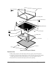
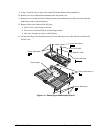
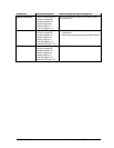
Table 2-7. Removing Display Components
Component Removal Procedures Additional Steps (See figure on page 4-5)
Display Bezel
Keyboard (page 2-8).
Heatsink (page 2-9).
Remove the bezel (page 2-11).
Reassembly Notes: Install the hinge end caps into
the case before attaching the bezel.
Display Bracket, Left,
Right, or Top
Keyboard (page 2-8).
Heatsink (page 2-9).
Display (page 2-11).
LCD module (page 2-11).
Display Cable
Keyboard (page 2-8).
Heatsink (page 2-9).
Display (page 2-11).
LCD module (page 2-11).
Reassembly Notes: Make sure the two-wire cable to
the inverter PCA is under the main display cable near
the hinge opening.
Display Case
Keyboard (page 2-8).
Heatsink (page 2-9).
Display (page 2-11).
LCD module (page 2-11).
Reassembly Notes: Make sure the two-wire cable to
the inverter PCA is under the main display cable near
the hinge opening.
Display Latch
Keyboard (page 2-8).
Heatsink (page 2-9).
Display (page 2-11).
LCD module (page 2-11).
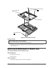
1. Press the middle of the top bracket away from the
latch until it unhooks from the case, then lift out the
bracket.
2. Turn the case so the latch is closest to you.
3. Use your thumb to push the latch away from you
until it rolls out of the case. This takes some force.
Reassembly Notes: Make sure the ends of the spring
point up when inserted into the case. Make sure the
latch locks in place.
End Cap
Keyboard (page 2-8).
Heatsink (page 2-9).
1. Remove the bezel (page 2-11).
2. Lift out the end cap.
Reassembly Notes: The mark molded into the cap
should be vertical when the display is laying flat.
Hinge
Keyboard (page 2-8).
Heatsink (page 2-9).
Display (page 2-11).
1. Remove the bezel (page 2-11).
2. Remove the four screws from the bottom corners of
the display brackets. Remove the hinges.
Reassembly Notes: Install each hinge so the brighter
half is attached to the display case.
Do not install the outer screw until the bezel is
attached.
Icon PCA
Plug-in module (page 2-3).
Hard drive (page 2-5).
Keyboard (page 2-8).
Heatsink (page 2-9).
Display (page 2-11).
Top case (page 2-14).
Remove the two screws that hold the PCA.
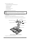
Inverter PCA
Keyboard (page 2-8).
Heatsink (page 2-9).
1. Do not remove the display assembly, but remove
the bezel as described (page 2-11).
2. Unplug the two cables from the inverter PCA.
3. Remove the screw from the PCA and remove the
PCA.
Reassembly Notes: Make sure the insulator covers
the inverter PCA.
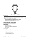
LCD Module
See page 2-11.