


iv HP OmniBook 7100
Figures
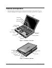
Figure 1-1. OmniBook - Front View....................................................................................................1-2
Figure 1-2. OmniBook - Side View .....................................................................................................1-2
Figure 1-3. OmniBook - Rear View.....................................................................................................1-3
Figure 1-4. Replaceable Module Diagram......................................................................................... 1-12
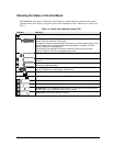
Figure 2-1. Removing the Battery or Module......................................................................................2-3
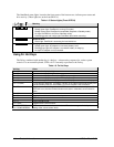
Figure 2-2. Removing a RAM Board...................................................................................................2-4
Figure 2-3. Removing the Hard Disk Drive.........................................................................................2-5
Figure 2-4. Installing a Hard Drive in the Case ...................................................................................2-6
Figure 2-5. Removing the Keyboard....................................................................................................2-8
Figure 2-6. Removing the Heatsink ...................................................................................................2-10
Figure 2-7. Removing the Display Assembly ....................................................................................2-11
Figure 2-8. Removing the LCD Module............................................................................................ 2-13
Figure 2-9. Removing the Top Case ..................................................................................................2-15
Figure 2-10. Removing the Motherboard (Part 1)..............................................................................2-16
Figure 2-11. Removing the Motherboard (Part 2)..............................................................................2-17
Figure 2-12. Removing the BIOS IC .................................................................................................2-20
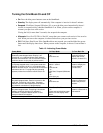
Figure 3-1. Basic Troubleshooting Steps.............................................................................................3-2
Figure 3-2. OmniBook Diagnostic Screens — Basic and Advanced.................................................3-11
Figure 3-3. Serial and Parallel Loopback Connectors........................................................................3-13
Figure 3-4. DMI Components............................................................................................................3-21
Figure 4-1. Exploded View..................................................................................................................4-2
Figure 4-2. Display Components .........................................................................................................4-5
Figure 4-3. Top Case Components ......................................................................................................4-6
Figure 4-4. Motherboard-Related Components ...................................................................................4-6
Tables
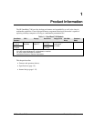
Table 1-1. OmniBook 7100 Models ....................................................................................................1-1
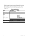
Table 1-2. Product Comparisons..........................................................................................................1-3
Table 1-3. Activating Power Modes ....................................................................................................1-4
Table 1-4. Status Panel Indicators (Icon PCA)....................................................................................1-5
Table 1-5. Status Lights (Front-IR PCA).............................................................................................1-6
Table 1-6. Fn Hot Keys........................................................................................................................1-6
Table 1-7. System Interrupts................................................................................................................1-7
Table 1-8. System Memory..................................................................................................................1-8
Table 1-9. System Input/Output Addresses (100-3FF) ........................................................................1-8
Table 1-10. DMA Channels.................................................................................................................1-8
Table 1-11. OmniBook 7100 Specifications........................................................................................1-9
Table 1-12. OmniBook 7100 Accessories .........................................................................................1-11
Table 1-13. Functional Structure........................................................................................................1-13
Table 2-1. Removal Cross-Reference ..................................................................................................2-1
Table 2-2. Required Equipment...........................................................................................................2-2
Table 2-3. Recommended Screw Torques........................................................................................... 2-2
Table 2-4. RAM Board Replacement Part Numbers ...........................................................................2-4
Table 2-5. Hard Disk Drive Replacement Part Numbers.....................................................................2-5
Table 2-6. Replacing Small Parts (User-Replaceable).........................................................................2-7
Table 2-7. Removing Display Components.......................................................................................2-21
Table 2-8. Removing Top Case Components....................................................................................2-22
Table 2-9. Removing Bottom Case Components...............................................................................2-23
Table 3-1. Scope of Diagnostic Tools..................................................................................................3-4