


HP OmniBook 7100 Removal and Replacement 2-23
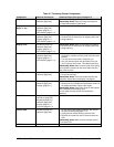
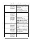
Table 2-9. Removing Bottom Case Components
Component Removal Procedures Additional Steps (See figure on page 4-6)
Audio Heatsink
Plug-in module (page 2-3).
Hard drive (page 2-5).
Keyboard (page 2-8).
Heatsink (page 2-9).
Display (page 2-11).
Top case (page 2-14).
Motherboard (page 2-15).
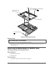
1. Remove the five screws from the PCMCIA shield
and remove the shield.
2. On the bottom of the motherboard, remove the four
screws that hold the PCMCIA socket. Do not lose
the mylar washers.
3. Unplug the PCMCIA socket from the motherboard.
4. Unplug the audio PCA from the motherboard.
5. Lift off the audio heatsink.
Reassembly Notes: Be sure the audio heatsink is
properly installed before installing the audio PCA.
Be sure to install the grounding clip on the PCMCIA
screw next to the volume control.
Audio Jack Cover
Plug-in module (page 2-3).
Hard drive (page 2-5).
Keyboard (page 2-8).
Heatsink (page 2-9).
Display (page 2-11).
Top case (page 2-14).
Motherboard (page 2-15).
On the bottom of the motherboard, remove the screw
from the audio jack cover and remove the cover.
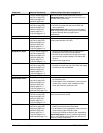
Audio PCA
Plug-in module (page 2-3).
Hard drive (page 2-5).
Keyboard (page 2-8).
Heatsink (page 2-9).
Display (page 2-11).
Top case (page 2-14).
Motherboard (page 2-15).
1. Remove the five screws from the PCMCIA shield
and remove the shield.
2. On the bottom of the motherboard, remove the four
screws that hold the PCMCIA socket.
3. Unplug the PCMCIA socket from the motherboard.
4. Unplug the audio PCA from the motherboard.
Reassembly Notes: Be sure the audio heatsink is
properly installed before installing the audio PCA.
Be sure to install the grounding clips on the PCMCIA
screws. Make sure they do not touch any nearby
components.
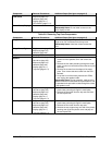
Bottom Case
See page 2-15.
CPU (MMO) Fence
Plug-in module (page 2-3).
Hard drive (page 2-5).
Keyboard (page 2-8).
Heatsink (page 2-9).
Display (page 2-11).
Top case (page 2-14).
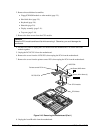
1. Unplug the DC-DC PCA.
2. Remove the screw from the LVDS PCA and unplug
the PCA.
3. Remove the three screws from the CPU module.
4. Lift the CPU fence to unplug the CPU module from
the motherboard. Lift out the fence and module
together.
CPU Module (MMO)
Plug-in module (page 2-3).
Hard drive (page 2-5).
Keyboard (page 2-8).
Heatsink (page 2-9).
Display (page 2-11).
Top case (page 2-14).
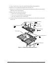
1. Remove the three screws from the CPU module.
2. Lift the CPU fence to unplug the CPU module from
the motherboard. Lift out the fence and module
together.
Caution: When installing the module, press directly
above the connectors. Otherwise, you could damage
pressure-sensitive components.
Caution: Replace any heatsink thermal pads that are
damaged.
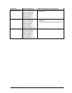
DC-DC PCA
Plug-in module (page 2-3).
Hard drive (page 2-5).
Keyboard (page 2-8).
Heatsink (page 2-9).
Display (page 2-11).
Top case (page 2-14).
Unplug the PCA from the motherboard.