


2-24 Removal and Replacement HP OmniBook 7100
Component Removal Procedures Additional Steps (See figure on page 4-6)
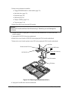
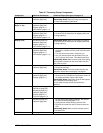
Fan
Plug-in module (page 2-3).
Hard drive (page 2-5).
Keyboard (page 2-8).
Heatsink (page 2-9).
Remove the three screws at the face of the fan.
Reassembly Notes: Install the fan wires next to the
rounded corner of the block.
Front-IR PCA
Plug-in module (page 2-3).
Hard drive (page 2-5).
Keyboard (page 2-8).
Heatsink (page 2-9).
Display (page 2-11).
Top case (page 2-14).
1. Unplug the front-IR cable from the motherboard.
2. Remove the screw from the front-IR PCA and
remove the PCA.
Reassembly Notes: Make sure the front-IR cable is
taped along the top of the housing and is retained by
the plastic tab near where it plugs into the
motherboard.
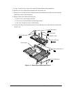
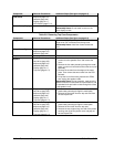
Heatsink, CPU
See page 2-9.
Hinge Mount, Left
Plug-in module (page 2-3).
Hard drive (page 2-5).
Keyboard (page 2-8).
Heatsink (page 2-9).
Display (page 2-11).
Top case (page 2-14).
Remove the five screws holding the hinge mount,
including two behind the I/O door.
Hinge Mount, Right
Plug-in module (page 2-3).
Hard drive (page 2-5).
Keyboard (page 2-8).
Heatsink (page 2-9).
Display (page 2-11).
Top case (page 2-14).
1. Remove the two screws from the hinge mount
holding the LVDS PCA and motherboard.
2. Remove the two screws from the top of the hinge
mount and two screws holding it from behind the
I/O door.
3. Slide out the hinge mount.
LVDS PCA
Plug-in module (page 2-3).
Hard drive (page 2-5).
Keyboard (page 2-8).
Heatsink (page 2-9).
Display (page 2-11).
Top case (page 2-14).
1. Unplug the DC-DC PCA from the motherboard.
2. Remove the screw from the LVDS PCA and unplug
the PCA from the motherboard.
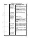
Motherboard
See page 2-15.
Motherboard Frame
Plug-in module (page 2-3).
Hard drive (page 2-5).
Keyboard (page 2-8).
Heatsink (page 2-9).
Display (page 2-11).
Top case (page 2-14).
Motherboard (page 2-15).
1. Remove the remaining screw at the front edge of
the PCMCIA shield.
2. On the bottom of the motherboard, remove the two
screws at the corners of the motherboard. One
screw also holds the audio jack cover.
PCMCIA Shield
Plug-in module (page 2-3).
Hard drive (page 2-5).
Keyboard (page 2-8).
Heatsink (page 2-9).
Display (page 2-11).
Top case (page 2-14).
Remove the three remaining screws from the PCMCIA
shield and remove the shield.
PCMCIA Socket
Plug-in module (page 2-3).
Hard drive (page 2-5).
Keyboard (page 2-8).
Heatsink (page 2-9).
Display (page 2-11).
Top case (page 2-14).
Motherboard (page 2-15).
1. Remove the three remaining screws from the
PCMCIA shield and remove the shield.
2. On the bottom of the motherboard, remove the four
screws that hold the PCMCIA socket.
3. Unplug the PCMCIA socket from the motherboard.
Reassembly Notes: Be sure to install the grounding
clips on the PCMCIA screws. Make sure they do not
touch any nearby components.