


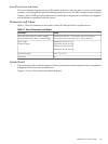
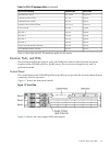
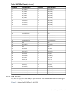
Table 1-6 PCI I/O Hardware Paths (continued)
HP-UX PathMAPPER PathPCI Card Functionality
0/1/1/1.2.00/1/1/1.2.0Internal SCSI - Slot 2
0/1/1/00/1/1/0Channel A Ultra 3 SCSI
0/1/1/10/1/1/1Channel B Ultra 3 SCSI
0/1/1/1.x.y0/1/1/1.x.yExternal, Ultra 3 SCSI LVD/SE
0/1/2/00/1/2/0Core LAN Gb
0/4/1/00/4/1/0PCI Slot 1
0/3/1/00/3/1/0PCI Slot 2
0/2/1/00/2/1/0PCI Slot 3
0/6/1/00/6/1/0PCI Slot 4
0/7/1/00/7/1/0UPS, Communications Controller
0/7/1/10/7/1/1Local/Remote Serial Controller
Table 1-6 describes the PCI I/O hardware paths for the server.
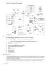
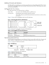
Controls, Ports, and LEDs
This section describes the controls, ports, and indicators found on the front and rear panel
locations of the HP 9000 rp3410 or rp3440 server. The servers are designed to be rack- or
pedestal-mounted.
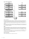
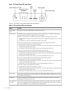
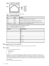
Control Panel
The control panel of the HP 9000 rp3410 and rp3440 servers provide the controls and indicators
commonly used for operation.
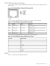
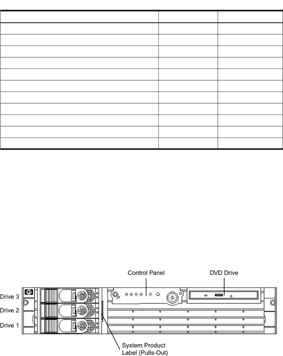
Figure 1-7 shows the front panel details.
Figure 1-7 Front View
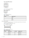
Figure 1-8 shows the control panel LEDs and buttons.
Controls, Ports, and LEDs 31