


Rear Panel
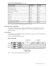
The rear panel of the HP 9000 rp3410 and rp3440 servers includes communication ports, I/O
ports, AC power connector, and the locator LED/button. Additional LEDs located on the rear
panel of the HP 9000 rp3410 and rp3440 servers signal the operational status of:
• 10/100/1000 Base-T Ethernet LAN
• iLO MP card LAN
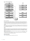
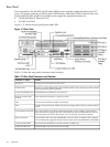
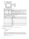
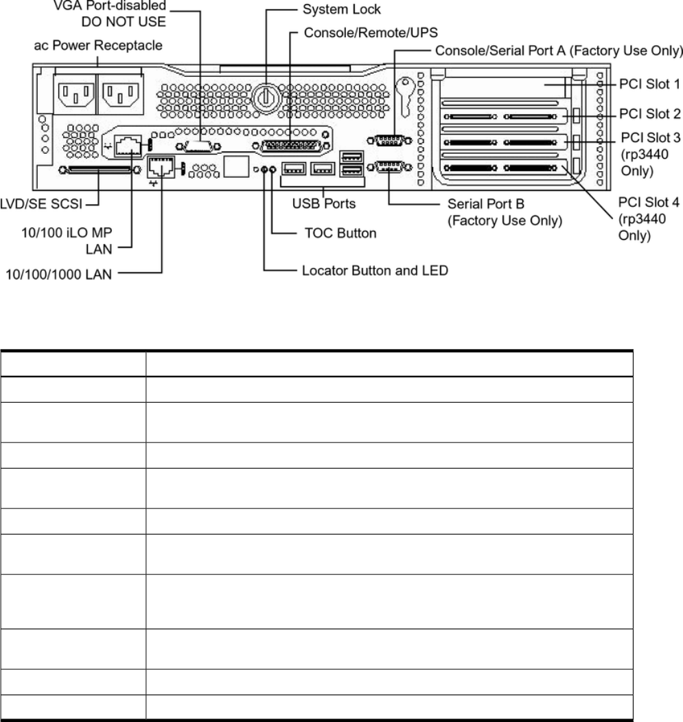
Figure 1-11 shows the rear panel ports and LEDs.
Figure 1-11 Rear View
Table 1-10 lists the rear-panel connectors and switches.
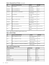
Table 1-10 Rear Panel Connectors and Switches
FunctionConnector or Switch
Primary power connection for the server.AC power
68-pin, low-voltage differential, single-ended U160SCSI. This connector provides external
SCSI connection on SCSI Channel B.
LVD/SE SCSI
10/100/1000 base-T Ethernet LAN connector.(1 GB) 10/100/1000 LAN
9-pin male serial connectors – factory use only.Serial A (console) and
Serial B
Four universal serial bus (USB 2.0) connectors.USB
Transfer of Control button. Halts all system processing and I/O activity and restarts the
system.
TOC
The Locator button and LED are used to help locate a server within a rack of servers.
When the button is engaged, the blue LED illuminates and an additional blue LED on
the front panel of the server illuminates. You can remotely activate this function.
Locator Button and LED
15-pin female video connector. DISABLED—DO NOT USE. To enable video capability,
you must obtain thesupported A6150 video PCI card. See enclosedReadMe, A6150-90001.
Video (not used)
25-pin female serial data bus connector for the iLO MP card.Console/remote/UPS
10 Mb/100 Mb LAN connector for the iLO MP.10/100 iLO MP LAN
34 Overview