


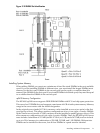
at less than optimum speed. PCI slots are numbered 1 (top of card cage) through 4 (bottom of
card cage). See the labels on the rear panel of the chassis for correct PCI slot number identification.
Installing a PCI Card
To install a PCI card, follow these steps:
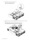
1. Remove the cover. (See “Removing and Replacing the Top Cover on a Rack-Mounted Server”
(page 53).)
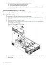
2. Remove the PCI cage. (See “Removing the PCI Card Cage” (page 74).)
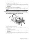
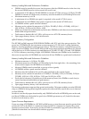
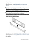
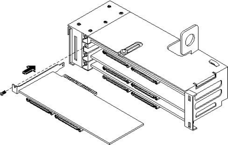
3. Grasp the edges of the PCI card to be installed and evenly press the card into the PCI
backplane connector.
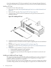
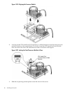
Figure 3-34 Installing a PCI Card
4. Connect any internal cables that are required by the PCI card.
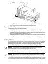
5. Install the accessory card holder and secure in place by tightening the associated bulkhead
screws.
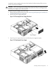
6. Reinstall the PCI cage. (See “Replacing the PCI Card Cage” (page 75).)
7. Replace the cover. (See “Removing and Replacing the Top Cover on a Rack-Mounted Server”
(page 53).)
8. Verify the PCI card installation by using the system utilities.
• Use the iLO MP commands to verify operation.
• Use the BCH commands to verify operation.
• Use diagnostics provided by the offline diagnostic environment to exercise the card
added.
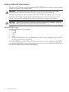
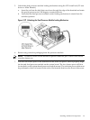
Installing an Additional Power Supply
The supported configuration of the HP 9000 rp3410 and rp3440 servers requires a minimum of
one power supply to be installed. A second, optional hot-swappable power supply, can be
installed to provide redundant (N+1) capability.
The power supplies in the server are hot-swappable; that is, if one power supply stops working
or exhibits voltage problems, the remaining supply can support the server until the failed unit
76 Installing the System