24-15
Cisco Systems Intelligent Gigabit Ethernet Switch Modules for the IBM BladeCenter, Software Configuration Guide
24R9746
Chapter 24 Configuring EtherChannels and Layer 2 Trunk Failover
Displaying EtherChannel, PAgP, and LACP Status
Displaying EtherChannel, PAgP, and LACP Status
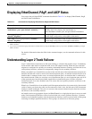
You can use the privileged EXEC commands described in Table 24-3 to display EtherChannel, PAgP,
and LACP status information:
For detailed information about the fields in the command outputs, see the command reference for this
release.
Understanding Layer 2 Trunk Failover
Layer 2 trunk failover, also known as link-state tracking, is a feature that provides Layer 2 redundancy
in the network when used in conjunction with server NIC adapter teaming. When the server network
adapters are configured in a primary or secondary relationship known as teaming, and if the link is lost
on the primary interface, connectivity transparently changes to the secondary interface.
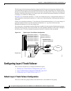
When you enable Layer 2 trunk failover on the switch, the link state of the internal downstream ports are
bound to the link state of one or more of the external upstream ports. An internal downstream port is an
interface that is connected to the server. An external upstream port is an interface that is connected to
the external network. When you associate a set of downstream ports to a set of upstream ports and if all
of the upstream ports become unavailable, trunk failover automatically puts all of the associated
downstream ports in an error-disabled state. This causes the server primary interface to failover to the
secondary interface.
When Layer 2 trunk failover is not enabled, and if the upstream interfaces lose connectivity, (the external
switch or router goes down, the cables are disconnected or link is lost), the link state of the downstream
interfaces remain unchanged. The server is not aware that external connectivity has been lost and does
not failover to the secondary interface.
An interface can be an aggregation of ports (an EtherChannel) or a single physical port in access or trunk
mode. Each downstream interface can be associated with one or more upstream interfaces. Upstream
interfaces can be bundled together, and each downstream interface can be associated with a single group
consisting of multiple upstream interfaces. These groups are referred to as link-state groups.
Table 24-3 Commands for Displaying EtherChannel, PAgP, and LACP Status
Command Description
show etherchannel [channel-group-number] {detail |
load-balance | port | port-channel | summary}
Displays EtherChannel information in a detailed and one-line
summary form. Also displays the load-balance or
frame-distribution scheme, port, and port-channel information.
show pagp [channel-group-number] {counters |
internal | neighbor}
1
1. You can clear PAgP channel-group information and traffic filters by using the clear pagp {channel-group-number [counters] | counters} privileged
EXEC command.
Displays PAgP information such as traffic information, the
internal PAgP configuration, and neighbor information.
show lacp [channel-group-number] {counters |
internal | neighbor}
2
2. You can clear LACP channel-group information and traffic filters by using the clear lacp {channel-group-number [counters] | counters} privileged
EXEC command.
Displays LACP information such as traffic information, the
internal PAgP configuration, and neighbor information.


