


Chapter 12. Performance considerations 263
complex, server 1. This affinity is established at creation of an extent pool. For details see
Chapter 10, “The DS Storage Manager - logical configuration” on page 189.
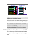
Each single I/O enclosure itself contains six Fibre Channel adapters:
Two DAs which install in pairs
Four HAs which install as required
Each adapter itself contains four Fibre Channel ports.
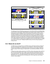
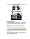
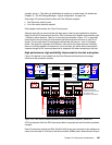
Although each HA can communicate with each server, there is some potential to optimize
traffic on the RIO-G interconnect structure. RIO-G provides a full duplex communication with
1 GB/sec in either direction. There is no such thing as arbitration. Figure 12-7 on page 262
shows that the two left-most I/O enclosures might communicate with server 0, each in full
duplex. The two right-most I/O enclosures communicate with server 1, also in full duplex
mode. This results in a potential of 8 GB/sec in total just for this single structure. Basically
there is no affinity between HA and server. As we see later, the server which owns certain
volumes through its DA, communicates with its respective HA when connecting to the host.
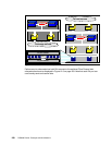
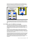
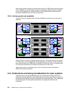
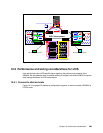
High performance, high availability interconnect to the disk subsystem
Figure 12-8 depicts in some detail how the Fibre Channel switched back-end storage
connects to the processor complex.
Figure 12-8 Fibre Channel switched backend connect to processor complexes - partial view
All I/O enclosures within the RIO interconnect fabric are equally served from either processor
complex.
Each I/O enclosure contains two DAs. Each DA with its four ports connects to four switches to
reach out to two sets of 16 drives or disk drive modules (DDMs) each. Note that each 20-port
ooo
20 port switch
20 port switch
16 DDM
RIO-G Module
RIO-G Module
ooo
20 port switch
20 port switch
16 DDM
DA
RIO-G Interconnect
DA
RIO-G Module
POWER5 2-way SMP
Processor
Memory
Processor
L1,2
Memory
L3
Memory
L1,2
Memory
POWER5 2-way SMP
Memory
L3
Memory
RIO-G Module
Processor
Processor
L1,2
Memory
L1,2
Memory
Note that DA and HA
positions in I/O enclosures
are shown to suit
the intention of the figure
Server 1
Server 0