


22 DS8000 Series: Concepts and Architecture
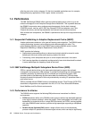
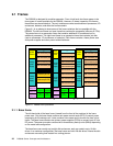
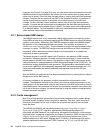
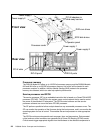
Figure 2-2 Rack operator panel
You will note that there is not a power on/off switch on the operator panel. This is because
power sequencing is managed via the S-HMC. This is to ensure that all data in non-volatile
storage (known as modified data) is de-staged properly to disk prior to power down. It is thus
not possible to shut down or power off the DS8000 from the operator panel (except in an
emergency, with the EPO switch mentioned previously).
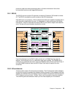
2.2 Architecture
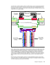
Now that we have described the frames themselves, we use the rest of this chapter to explore
the technical details of each of the components. The architecture that connects these
components is pictured in Figure 2-3 on page 23.
In effect, the DS8000 consists of two processor complexes. Each processor complex has
access to multiple host adapters to connect to channel, FICON, and ESCON hosts. Each
DS8000 can potentially have up to 32 host adapters. To access the disk subsystem, each
complex uses several four-port Fibre Channel arbitrated loop (FC-AL) device adapters. A
DS8000 can potentially have up to sixteen of these adapters arranged into eight pairs. Each
adapter connects the complex to two separate switched Fibre Channel networks. Each
switched network attaches disk enclosures that each contain up to 16 disks. Each enclosure
contains two 20-port Fibre Channel switches. Of these 20 ports, 16 are used to attach to the
16 disks in the enclosure and the remaining four are used to either interconnect with other
enclosures or to the device adapters. Each disk is attached to both switches. Whenever the
device adapter connects to a disk, it uses a switched connection to transfer data. This means
that all data travels via the shortest possible path.
The attached hosts interact with software which is running on the complexes to access data
on logical volumes. Each complex will host at least one instance of this software (which is
called a
server), which runs in a logical partition (an LPAR). The servers manage all read and
write requests to the logical volumes on the disk arrays. During write requests, the servers
Line cord
indicators
Fault indicator
EPO switch cover