


Chapter 4. RAS 69
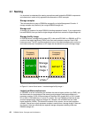
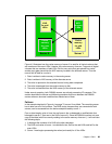
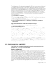
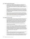
Figure 4-3 Normal data flow
Figure 4-3 illustrates how the cache memory of server 0 is used for all logical volumes that
are members of the even LSSs. Likewise, the cache memory of server 1 supports all logical
volumes that are members of odd LSSs. But for every write that gets placed into cache,
another copy gets placed into the NVS memory located in the alternate server. Thus the
normal flow of data for a write is:
1. Data is written to cache memory in the owning server.
2. Data is written to NVS memory of the alternate server.
3. The write is reported to the attached host as having been completed.
4. The write is destaged from the cache memory to disk.
5. The write is discarded from the NVS memory of the alternate server.
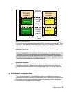
Under normal operation, both DS8000 servers are actively processing I/O requests. This
section describes the failover and failback procedures that occur between the DS8000
servers when an abnormal condition has affected one of them.
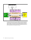
Failover
In the example depicted in Figure 4-4 on page 70, server 0 has failed. The remaining server
has to take over all of its functions. The RAID arrays, because they are connected to both
servers, can be accessed from the device adapters used by server 1.
From a data integrity point of view, the real issue is the un-destaged or modified data that
belonged to server 1 (that was in the NVS of server 0). Since the DS8000 now has only one
copy of that data (which is currently residing in the cache memory of server 1), it will now take
the following steps:
1. It destages the contents of its NVS to the disk subsystem.
2. The NVS and cache of server 1 are divided in two, half for the odd LSSs and half for the
even LSSs.
3. Server 1 now begins processing the writes (and reads) for
all the LSSs.
Server 0
Server 1
Cache
memory
for even
LSSs
NVS
for odd
LSSs
NVS
for even
LSSs
Cache
memory
for odd
LSSs