


Chapter 4. RAS 63
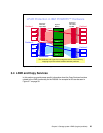
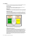
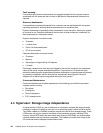
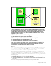
Figure 4-2 Dual image mode
In Figure 4-2 we have two storage facility images (SFIs). The upper server 0 and upper server
1 form SFI 1. The lower server 0 and lower server 1 form SFI 2. In each SFI, server 0 is the
darker color (green) and server 1 is the lighter color (yellow). SFI 1 and SFI 2 may share
common hardware (the processor complexes) but they are completely separate from an
operational point of view.
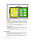
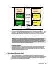
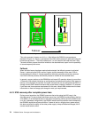
Processor complex
A processor complex is one p5 570 pSeries system unit. Two processor complexes form a
redundant pair such that if either processor complex fails, the servers on the remaining
processor complex can continue to run the storage image. In an ESS 800, we would have
referred to a processor complex as a cluster.
4.2 Processor complex RAS
The p5 570 is an integral part of the DS8000 architecture. It is designed to provide an
extensive set of reliability, availability, and serviceability (RAS) features that include improved
fault isolation, recovery from errors without stopping the processor complex, avoidance of
recurring failures, and predictive failure analysis.
Note: You may think that the lower server 0 and lower server 1 should be called server 2
and server 3. While this may make sense from a numerical point of view (for example,
there are four servers so why not number them from 0 to 3), but each SFI is not aware of
the other’s existence. Each SFI must have a server 0 and a server 1, regardless of how
many SFIs or servers there are in a DS8000 storage unit.
Processor
complex 0
Processor
complex 1
Storage
facility
image 1
Server 0
Storage
facility
image 2
Server 0
Server 1
Server 1
LPARs
LPARs