


34 DS8000 Series: Concepts and Architecture
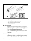
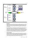
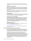
Figure 2-12 Disk enclosure switched connections
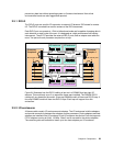
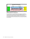
DS8000 switched FC-AL implementation
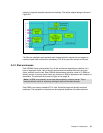
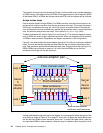
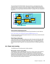
For a more detailed look at how the switched disk architecture expands in the DS8000 you
should refer to Figure 2-13 on page 35. It depicts how each DS8000 device adapter connects
to two disk networks called loops. Expansion is achieved by adding enclosures to the
expansion ports of each switch. Each loop can potentially have up to six enclosures, but this
will vary depending on machine model and DA pair number. The front enclosures are those
that are physically located at the front of the machine. The rear enclosures are located at the
rear of the machine.
server 0
device
adapter
Fibre channel switch
server 1
device
adapter
Switched connections
Fibre channel switch