


Chapter 4. RAS 77
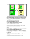
RAID-10 theory
RAID-10 provides high availability by combining features of RAID-0 and RAID-1. RAID-0
optimizes performance by striping volume data across multiple disk drives at a time. RAID-1
provides disk mirroring, which duplicates data between two disk drives. By combining the
features of RAID-0 and RAID-1, RAID-10 provides a second optimization for fault tolerance.
Data is striped across half of the disk drives in the RAID-1 array. The same data is also
striped across the other half of the array, creating a mirror. Access to data is preserved if one
disk in each mirrored pair remains available. RAID-10 offers faster data reads and writes than
RAID-5 because it does not need to manage parity. However, with half of the DDMs in the
group used for data and the other half to mirror that data, RAID-10 disk groups have less
capacity than RAID-5 disk groups.
RAID-10 implementation in the DS8000
In the DS8000 the RAID-10 implementation is achieved using either six or eight DDMs. If
spares exist on the array site, then six DDMs are used to make a three-disk RAID-0 array
which is then mirrored. If spares do not exist on the array site then eight DDMs are used to
make a four-disk RAID-0 array which is then mirrored.
Drive failure
When a disk drive module (DDM) fails in a RAID-10 array, the controller starts an operation to
reconstruct the data from the failed drive onto one of the hot spare drives. The spare that is
used will be chosen based on a smart algorithm that looks at the location of the spares and
the size and location of the failed DDM. Remember a RAID-10 array is effectively a RAID-0
array that is mirrored. Thus when a drive fails in one of the RAID-0 arrays, we can rebuild the
failed drive by reading the data from the equivalent drive in the other RAID-0 array.
While this data reconstruction is going on, the DA can still service read and write requests to
the array from the hosts. There may be some degradation in performance while the sparing
operation is in progress because some DA and switched network resources are being used to
do the reconstruction. Due to the switch-based architecture of the DS8000, this effect will be
minimal. Read requests for data on the failed drive should not be affected because they can
all be directed to the good RAID-1 array.
Write operations will not be affected. Performance of the RAID-10 array returns to normal
when the data reconstruction onto the spare device completes. The time taken for sparing
can vary, depending on the size of the failed DDM and the workload on the array and the DA.
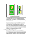
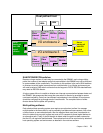
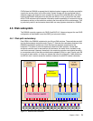
Arrays across loops
The DS8000 implements the concept of arrays across loops (AAL). With AAL, an array site is
actually split into two halves. Half of the site is located on the first disk loop of a DA pair and
the other half is located on the second disk loop of that DA pair. It is implemented primarily to
maximize performance. However, in RAID-10 we are able to take advantage of AAL to
provide a higher level of redundancy. The DS8000 RAS code will deliberately ensure that one
RAID-0 array is maintained on each of the two loops created by a DA pair. This means that in
the extremely unlikely event of a complete loop outage, the DS8000 would not lose access to
the RAID-10 array. This is because while one RAID-0 array is offline, the other remains
available to service disk I/O.
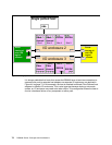
4.6.4 Spare creation
When the array sites are created on a DS8000, the DS8000 microcode determines which
sites will contain spares. The first four array sites will normally each contribute one spare to
the DA pair, with two spares being placed on each loop. In general, each device adapter pair
will thus have access to four spares.