


Chapter 2. Components 21
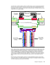
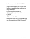
Between the disk enclosures and the processor complexes are two Ethernet switches, a
Storage Hardware Management Console (an S-HMC) and a keyboard/display module.
The base frame contains two processor complexes. These eServer p5 570 servers contain
the processor and memory that drive all functions within the DS8000. In the ESS we referred
to them as
clusters, but this term is no longer relevant. We now have the ability to logically
partition each processor complex into two LPARs, each of which is the equivalent of a Shark
cluster.
Finally, the base frame contains four I/O enclosures. These I/O enclosures provide
connectivity between the adapters and the processors. The adapters contained in the I/O
enclosures can be either device or host adapters (DAs or HAs). The communication path
used for adapter to processor complex communication is the RIO-G loop. This loop not only
joins the I/O enclosures to the processor complexes, it also allows the processor complexes
to communicate with each other.
2.1.2 Expansion frame
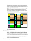
The left-hand side of each expansion frame (viewed from the front of the machine) is the
frame power area. The expansion frames do not contain rack power control cards; these
cards are only present in the base frame. They do contain a fan sense card to monitor the
fans in that frame. Each expansion frame contains two primary power supplies (PPS) to
convert the AC input into DC power. Finally, the power area may contain three battery backup
units (BBUs) depending on the model and configuration.
Each expansion frame can hold up to 16 disk enclosures which contain the disk drives. They
are described as
16-packs because each enclosure can hold 16 disks. In a maximum
configuration, an expansion frame can hold 256 disk drives. Above the disk enclosures are
cooling fans located in a cooling plenum.
An expansion frame can contain I/O enclosures and adapters if it is the first expansion frame
that is attached to either a model 922 or a model 9A2. The second expansion frame in a
model 922 or 9A2 configuration cannot have I/O enclosures and adapters, nor can any
expansion frame that is attached to a model 921. If the expansion frame contains I/O
enclosures, the enclosures provide connectivity between the adapters and the processors.
The adapters contained in the I/O enclosures can be either device or host adapters.
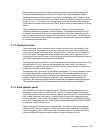
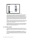
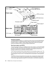
2.1.3 Rack operator panel
Each DS8000 frame features an operator panel. This panel has three indicators and an
emergency power off switch (an EPO switch). Figure 2-2 on page 22 depicts the operator
panel. Each panel has two line cord indicators (one for each line cord). For normal operation
both of these indicators should be on, to indicate that each line cord is supplying correct
power to the frame. There is also a fault indicator. If this indicator is illuminated you should
use the DS Storage Manager GUI or the Storage Hardware Management Console (S-HMC)
to determine why this indicator is on.
There is also an EPO switch on each operator panel. This switch is only for emergencies.
Tripping the EPO switch will bypass all power sequencing control and result in immediate
removal of system power. A small cover must be lifted to operate it. Do not trip this switch
unless the DS8000 is creating a safety hazard or is placing human life at risk.