


Intel® 41210 Serial to Parallel PCI Bridge Design Guide 19
Power Plane Layout 4
This chapter provides details on the decoupling and voltage planes needed to bias the 41210 Bridge
package.
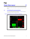
4.1 41210 Bridge Decoupling Guidelines
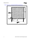
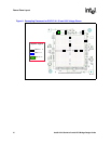
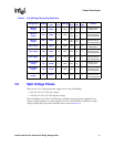
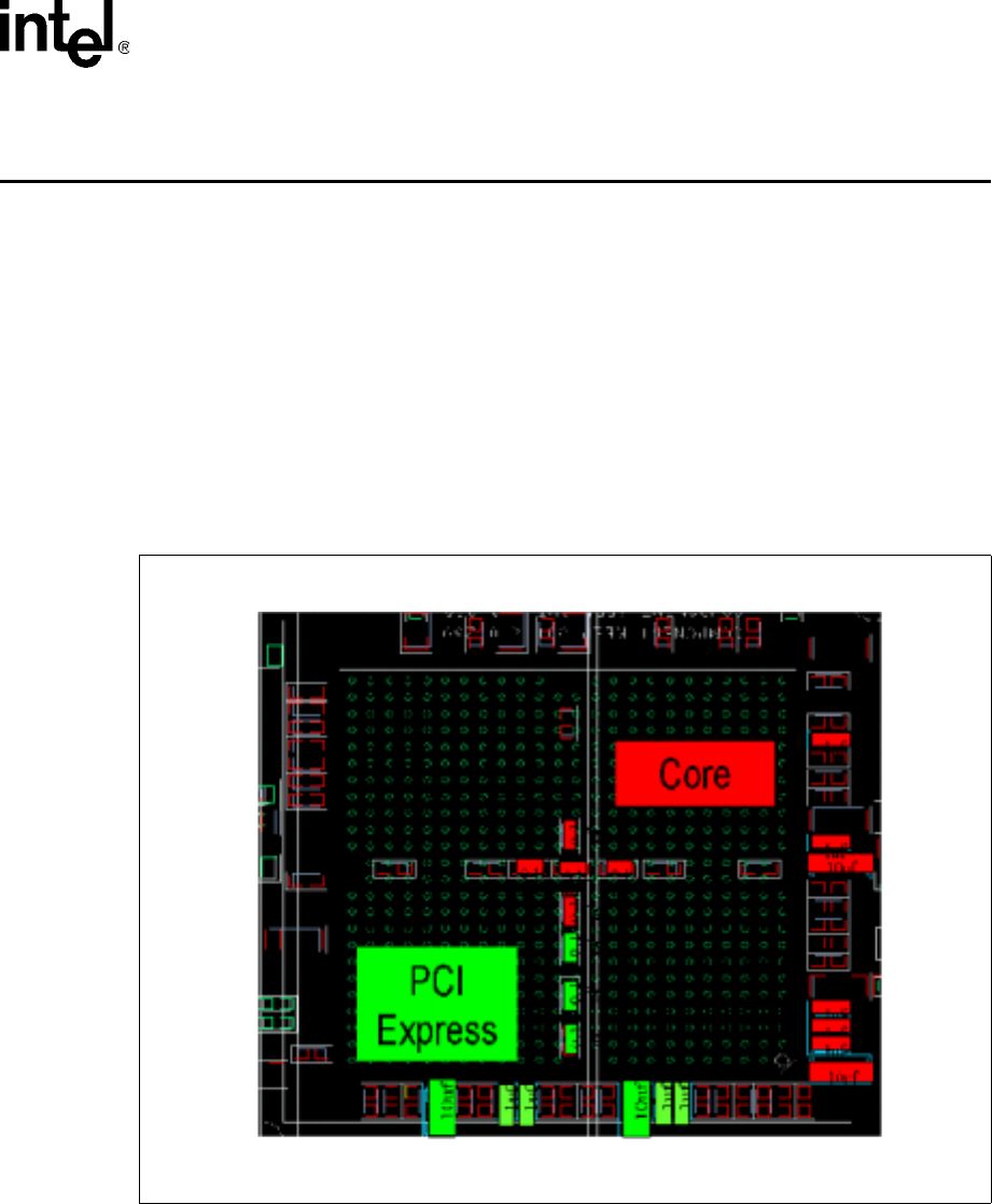
Table 2 lists the decoupling guidelines for the 41210 Bridge. Figure 8 and Figure 9 provide the
decoupling capacitors around the 41210 Bridge ball grid pins.
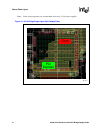
Figure 8. Decoupling Placement for Core and PCI Express Voltage Planes
B2713-01