


42 Intel® 41210 Serial to Parallel PCI Bridge Design Guide
PCI-X Layout Guidelines
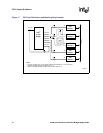
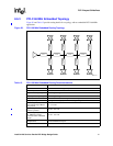
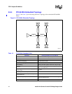
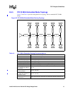
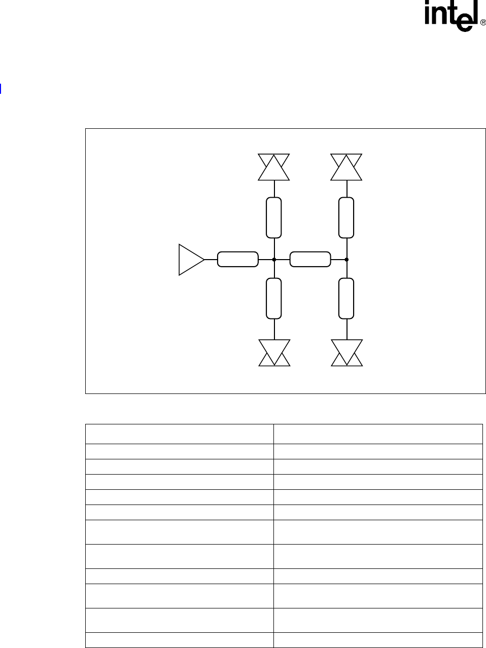
8.6.4 PCI 66 MHz Embedded Topology
Figure 21 and Table 13 provide routing details for a topology with an embedded PCI 66 MHz
design.
P
Figure 21. PCI 66 MHz Embedded Topology
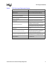
Table 13. PCI 66 MHz Embedded Table
Parameter Routing Guideline for Lower AD Bus
Reference Plane Route over an unbroken ground plane
Board Impedance 60 Ω +/- 15%
Microstrip Trace Spacing 18 mils center to center
Stripline Trace Spacing 12 mils center to center
Group Spacing Spacing from other groups: 25 mils min, edge to edge
Breakout
5 mils on 5 mils spacing. Maximum length of breakout
region can be 500 mils.
Trace Length 1 TL1: From 41210 Bridge signal Ball
to first junction
5.0” max
Trace Length TL2 between junctions 0.5” min - 3.5” max
Trace Length TL_EM1 to TL_EM4 from junction to
embedded devices
2.0” min - 3.0” max
Length Matching Requirements
Clocks coming from the clock driver must be length
matched to within 25 mils.
Number of vias 4 vias max.
B2722 -01
EM1
EM2
TL1
TL_EM2 TL_EM1
EM3
EM4
TL2
TL_EM4 TL_EM3