


Intel® 41210 Serial to Parallel PCI Bridge Design Guide 61
Design Guide Checklist
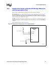
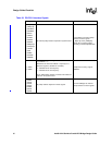
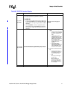
A_M66EN
B_M66EN
Controls frequency of the PCI segment when running
in conventional PCI mode (33 MHz or 66 MHz):
0 = 33 MHz PCI
1 = 66 MHz PCI
• Pull-up using a 8.2KΩ resistor when the PCI bus is
to operate at 66 MHz and not already pulled up by
system board. This signal is grounded for 33 MHz
operation.
• Connect M66EN to a 0.01 µF capacitor located
with-in 0.25 inches of the M66EN pin on the PCI
connector (for designs with secondary PCIX bus
slots only).
Sampled on the rising edge of
PERST#.
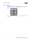
A_PCIXCAP
B_PCIXCAP
Connects directly to the PCIXCAP pin on the PCI slot.
Connect to VCC33 through an 8.2KΩ pullup resistor.
• Design without secondary PCI/PCI-
X Slot
— If there is at least one legacy
PCI device on the PCI/PCI-X
bus, tie this pin directly to
GND.
— If all devices are PCI-X
capable and there is at least
one PCI-X device that only
supports maximum PCI-X
66MHz on the secondary PCI
bus, pull down to GND
through 10K
Ω series resistor
parallel with a 0.01uF
capacitor.
— If all secondary PCI-X
devices (and the bus loading)
support PCI-X 133MHz,
connect PCIXCAP to 3.3V
through an 8.2K
Ω resistor
• Design with secondary PCI/PCI-X
Slot
— If there is at least one on
board legacy PCI device on
the secondary PCI bus, tie
this pin directly to GND.
—Else
•Pull up to 3.3V through a
8.2K
Ω resistor
•Connect this pin to
PCIXCAP (Pin B38) of the
PCI connector. (Assuming
bus loading supports up to
PCI-X 133MHz)
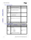
IDSEL The series resistor on IDSEL should be 200Ω ±5%.
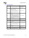
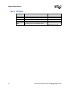
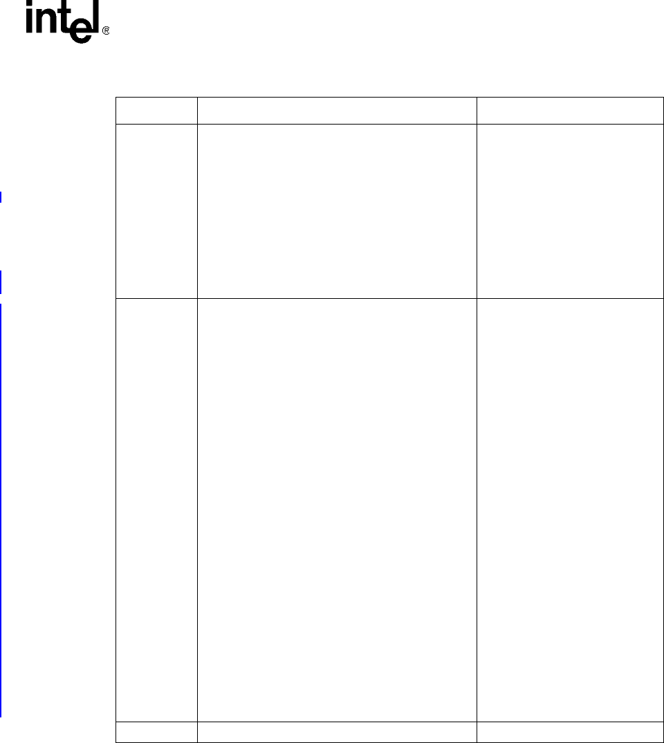
Table 20. PCI/PCI-X Interface Signals
Signals Recommendations Reason/Impact