


Intel® 41210 Serial to Parallel PCI Bridge Design Guide 7
About This Document 1
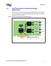
This document provides layout information and guidelines for designing platform or add-in board
applications with the Intel
®
41210 Serial to Parallel PCI Bridge (also called the 41210 Bridge). It is
recommended that this document be used as a guideline. Intel recommends employing best-known
design practices with board level simulation, signal integrity testing and validation for a robust
design.
Designers should note that this guide focuses upon specific design considerations for the 41210
Bridge and is not intended to be an all-inclusive list of all good design practices. Use this guide as
a starting point and use empirical data to optimize your particular design.
1.1 Terminology and Definitions
Table 1 provides a list of terms and definitions that may be useful when working with the 41210
Bridge product.
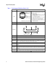
Table 1. Terminology and Definitions (Sheet 1 of 2)
Term Definition
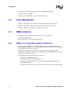
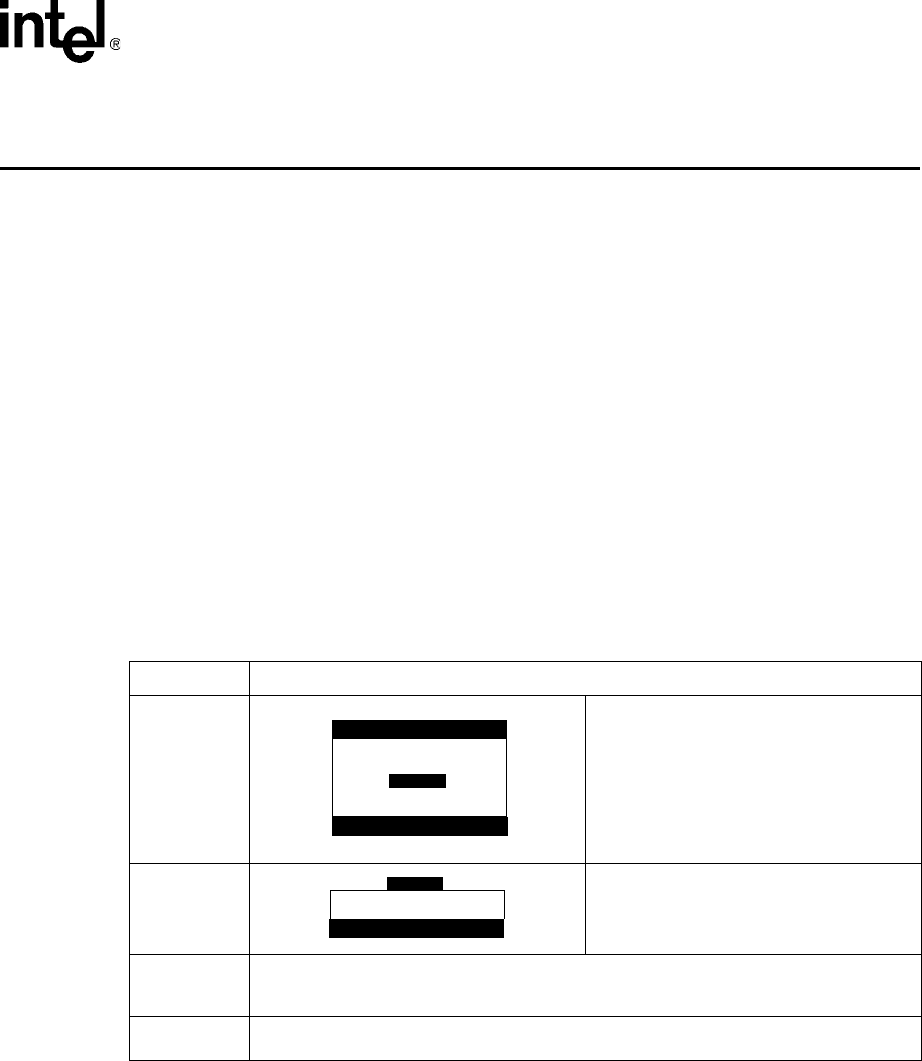
Stripline
Stripline in a PCB is composed of the
conductor inserted in a dielectric with GND
planes to the top and bottom.
NOTE: An easy way to distinguish stripline
from microstrip is that you need to
strip away layers of the board to view
the trace on stripline.
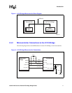
Microstrip
Microstrip in a PCB is composed of the
conductor on the top layer above the dielectric
with a ground plane below
Prepreg
Material used for the lamination process of manufacturing PCBs. It consists of a layer of
epoxy material that is placed between two cores. This layer melts into epoxy when heated and
forms around adjacent traces.
Core
Material used for the lamination process of manufacturing PCBs. This material is two sided
laminate with copper on each side. The core is an internal layer that is etched.