36 Intel® 41210 Serial to Parallel PCI Bridge Design Guide
PCI-X Layout Guidelines
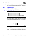
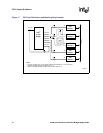
Figure 17. PCI Clock Distribution and Matching Requirements
B1499-04
PCI
Device 1
PCI
Device 2
PCI
Device 3
a
X0
A_CLKO0
PCI Bus
A_CLKIN
A_CLKO1
A_CLKO2
A_CLKO3
A_CLKO4
A_CLKO6
22
22
22
22
22
X3
X1
d
X2
PCI
Device 4
22
X4
PCI
Device 5
Intel
®
41210
Bridge
Notes:
– PCI Clock Lengths X0, X1, X2, X3 and X4 should be matched within 0.1 inch of each other.
– Minimum separation between two different CLKs, "d".
– Minimum separation between two segments of the same CLK line, "a".


