


28 Intel® 41210 Serial to Parallel PCI Bridge Design Guide
General Routing Guidelines
Note: Using stripline transmission lines may give better results than microstrip. This is due to the
difficulty of precisely controlling the dielectric constant of the solder mask, and the difficulty in
limiting the plated thickness of microstrip conductors, which can substantially increase cross-talk.
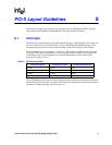
6.5.1 Differential Impedance
The PCI Express standard defines a 100 Ω differential impedance. This section provides some basic
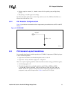
background information on the differential impedance calculations. In the cross section of
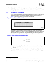
Figure 13 shows the cross section of two traces of a differential pair.
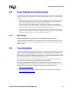
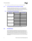
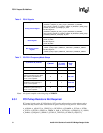
To calculate the coupled impedance requires a 2x2 matrix. The diagonal values in the matrix
represent the impedance of the traces to ground and the off-diagonal values provide a measure of
how tightly the traces are coupled. The “differential impedance is the value of the line-to-line
resistor terminator that optimally terminates pure differential signals.” The two by two matrix is
shown below as:
For a symmetric trace Z11 = Z22, the differential impedance can be calculated from this equation:
Z
differential
= 2(Z11-Z12)
For two traces to be symmetric, they must have the same width, thickness and height above the
ground plane.
1
With the traces terminated with the appropriate differential, impedance ringing is
minimized.
Figure 13. Cross Section of Differential Trace
B2716 -01
Ground reference plane
Figure 14. Two-by-two Differential Impedance Matrix
B2717 -01
Z
o
Z11 Z12
Z21 Z22
=
1. “Terminating Differential Signals on PCBs”, Steve Kaufer and Kelee Crisafulli, Printed Circuit Design, March 1999