


Intel® Server Board SE7320SP2 & Intel Server Board SE7525GP2 TPS Error Reporting and Handling
Revision 2.0
134
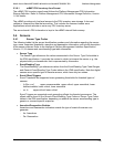
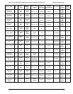
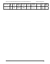
Bits 3:1 of the generator ID field define the format revision. The system software ID is a 7-bit
quantity. For events covered in this document, the system software IDs will be within the range
0x18-0x1F. System software ID of 0x18 indicates that OEM data byte 2 and 3 are encoded
using data format scheme revision 0. Note that the system software IDs in the range 0x10-0x1f
are reserved for the SMI handler. The IPMI specification reserves two distinct ranges for the
BIOS and the SMI handler. Since the distinction between the two is not very important, we use
the same values of generator ID’s for the BIOS as well as the SMI handler. Technically, the
FRB-2 event is not logged by the SMI handler, but it will use the same generator ID range as
memory errors.
6.1.3 Single-bit ECC Error Throttling Prevention
The system detects, corrects, and logs correctable errors. As long as these errors occur
infrequently, the system should continue to operate without a problem.
Occasionally, correctable errors are caused by a persistent failure of a single component. For
example, a broken data line on a DIMM would exhibit repeated errors until replaced. Although
these errors are correctable, continual calls to the error logger can throttle the system,
preventing any further useful work.
For this reason, the system counts certain types of correctable errors and disables reporting if
they occur too frequently. Correction remains enabled but calls to the error handler are disabled.
This allows the system to continue running, despite a persistent correctable failure. The BIOS
adds an entry to the event log to indicate that logging for that type of error has been disabled.
Such an entry indicates a serious hardware problem that must be repaired at the earliest
possible time.
6.2 Error Messages and Error Codes
The BIOS indicates the current testing phase during POST by writing a hex code to I/O location
80h. If errors are encountered, error messages or codes will either be displayed to the video
screen, or if an error has occurred prior to video initialization, errors will be reported through a
series of audio beep codes.
The error codes are defined by Intel and whenever possible are backward compatible with error
codes used on earlier platforms.
Most POST error codes are logged in the System Event Log.
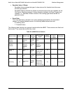
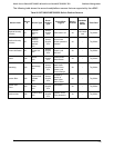
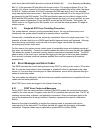
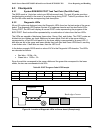
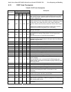
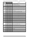
6.2.1 POST Error Codes and Messages
During POST after the video has been initialized, the BIOS outputs the current boot progress
codes on the video screen. Progress codes are 32-bit quantities plus optional data. The 32- bit
numbers include class, subclass, and operation information. Class and subclass point to the
type of the hardware that is being initialized. Operation represents the specific initialization
activity.
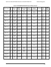
Based on the data bit availability to display the progress code, a progress code can be
customized to fit the data width. The higher the data bit, higher the granularity of allowable
information. Progress codes may be reported by system BIOS or option ROMs.