


Intel® Server Board SE7320SP2 & Intel Server Board SE7525GP2 TPS Functional Architecture
Revision 2.0
45
Note that this entire mechanism requires no software support once it has been programmed and
enabled, until the threshold detection has been triggered to request a data copy. Hardware will
detect the threshold initiating fail-over, and escalate the occurrence of that event as directed
(signal an SMI, generate an interrupt, or wait to be discovered via polling). Whatever software
routine responds to the threshold detection must select a victim DIMM (in case multiple DIMMs
have crossed the threshold prior to sparing invocation) and initiate the memory copy. Hardware
will automatically isolate the “failed” DIMM once the copy has completed. The data copy is
accomplished by address aliasing within the DDR control interface, thus it does not require
reprogramming of the DRAM row boundary (DRB) registers, nor does it require notification to
the operating system that anything has occurred in memory.
3.6 I/O Sub-System
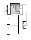
The I/O sub-system is made up of several components: the MCH providing the PCI-Express
interface and the Intel 6300ESB I/O Controller providing the interface for the onboard video
controller, Super IO chip, and Management Sub-system. This section describes the function of
each I/O interface and how they operate on the Intel Server Boards SE7320SP2 and
SE7525GP2.
3.6.1 PCI Subsystem
The primary I/O interface for the Server Boards SE7320SP2 and SE7525GP2 is PCI, with two
independent PCI bus segments. A PCI 33 MHz 32-bit bus segment (P32-A) with two connectors
and a PCI-X 64-bit / 66MHz segment (P64-A) are controlled through the Intel 6300ESB I/O
Controller. Additionally, one x4 PCI-Express (P64-Express4) bus segment controlled from the
MCH on the Intel Server Board SE7320SP2 is available. Or one x4 PCI-Express bus segment
and one x16 PCI-Express bus segment (P64-Express16) are available on the Intel Server Board
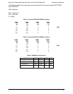
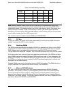
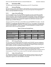
SE7525GP2. The table below lists the characteristics of the different PCI bus segments.
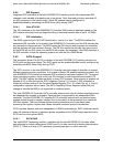
Table 8: PCI Bus Segment Characteristics
PCI Bus Segment Voltage Width Speed Type PCI I/O Card Slots
P32-A 5 V 32-bits 33 MHz PCI 2 slots
P64-A 3.3 V 64-bits 66 MHz PCI-X 2 slots
P64-Express4 1.6 V 64-bits x4 PCI-E 1 slot
P64-Express16 1.6 V 64-bits x16 PCI-E 1 slot (SE7525GP2 only)
3.6.1.1 P32-A: 32-bit, 33-MHz PCI Subsystem
All 32-bit, 33-MHz PCI I/O for the Intel Server Boards SE7320SP2 and server board
SE7525GP2s are directed through the Intel 6300ESB I/O Controller. The 32-bit, 33-MHz PCI
segment created by the Intel 6300ESB I/O Controller is known as the P32-A segment. The P32-
A segment supports the following devices:
• 2D/3D Graphics Accelerator: ATI* Rage XL Video Controller
• SIO Chip: National Semiconductor* PC87417 Super I/O
• Hardware monitoring sub-system: SMBUS
• Intel 82541 PCI Gigabit NIC
• 2 Expansion Slots