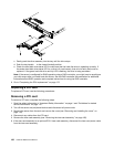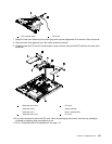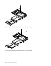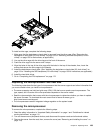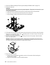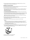
Removing a USB embedded hypervisor ash device
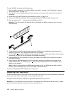
To remove a hypervisor ash device, complete the following steps:
1. Read the safety information in “Important Safety Information” on page 1 and “Guidelines for trained
service technicians” on page 115.
2. Turn off the server and peripheral devices and disconnect the power cords.
3. Remove the cover (see “Removing and installing the cover” on page 119).
4. Remove the riser-card assembly (see “Removing the riser-card assembly” on page 156).
5. Unlock the retention latch on the USB connector by squeezing the two retention clips toward each other
(see “System-board internal connectors” on page 108.
6. Grasp the ash device and pull to remove it from the connector.
7. Press down on the retention latch to return it to the locked position.
8. If you are instructed to return the ash device, follow all packaging instructions, and use any packaging
materials for shipping that are supplied to you.
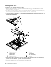
Installing a USB embedded hypervisor ash device
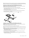
To install a hypervisor ash device, complete the following steps:
1. Read the safety information in “Important Safety Information” on page 1 and “Guidelines for trained
service technicians” on page 115.
2. Turn off the server and peripheral devices and disconnect the power cords.
3. Remove the cover (see “Removing and installing the cover” on page 119).
4. Remove the riser-card assembly (see “Removing the riser-card assembly” on page 156) (see
“System-board internal connectors” on page 108
.
5. Unlock the retention latch on the USB connector by squeezing the two retention clips toward each other
(see “System-board internal connectors” on page 108.
6. Align the ash device with the USB connector on the system board and push it into the USB connector
until it is rmly seated.
7. Press down on the retention latch to lock the ash device into the USB connector.
8. Install the riser-card assembly (see “Installing the riser-card assembly” on page 157).
9. Go to “Completing the FRU replacement” on page 172.
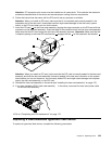
Replacing the operator information panel assembly
To replace the operator information panel assembly, use the following procedures:
Removing the operator information panel assembly
To remove the operator information panel assembly, complete the following steps.
1. Read the safety information in “Important Safety Information” on page 1 and “Guidelines for trained
service technicians” on page 115.
2. Turn off the server and peripheral devices, and disconnect the power cords and all external cables.
3. Remove the server from the rack and remove the cover (see “Removing and installing the cover” on
page 119).
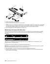
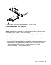
4. Disconnect both cables from the operator information panel assembly.
5. Remove the screws that secure the operator information panel assembly to the DVD bay housing.
134 Hardware Maintenance Manual


