


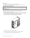
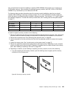
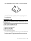
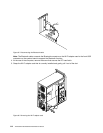
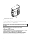
10. Carefully slide the system board so that it can be released from the mounting studs that secure the
system board in place.
11. Lift the system board out of the chassis.
12. Remove the microprocessor from the failing system board and install it on the new system board. See
“Replacing the microprocessor” on page 101.
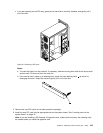
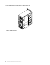
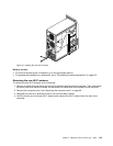
13. Install the new system board into the chassis by aligning the eight mounting studs in the chassis with the
corresponding holes in the new system board. Carefully slide the new system board into the chassis until
it is secured in place by the mounting studs. Then, install the eight screws to secure the system board.
14. Install the heat sink and fan assembly and connect the heat sink and fan assembly cable to the new
system board. See “Replacing the heat sink and fan assembly” on page 99
.
15. Install the hard disk drive . See “Replacing the hard disk drive” on page 87.
16. Install the power supply assembly. See “Replacing the power supply assembly” on page 96.
17. Install all memory modules and PCI cards removed from the failing system board on the new system
board. See “Installing or replacing a memory module” on page 108 and “Installing or replacing a PCI
card” on page 104
.
18. Reconnect all remaining cables to the system board. See “Locating parts on the system board”
on page 73
.
19. To complete the replacement, go to “Completing the parts replacement” on page 122.
The failing system board must be returned with a microprocessor socket cover to protect the pins during
shipping and handling.
To install the microprocessor socket cover, do the following:
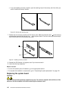
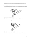
1. Release the lever securing the microprocessor retainer and open the retainer to access the
microprocessor.
2. Grasp the microprocessor on the sides and lift it straight up and out of the socket. Do not touch the
contacts on the microprocessor socket.
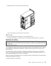
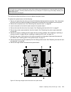
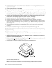
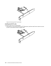
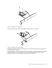
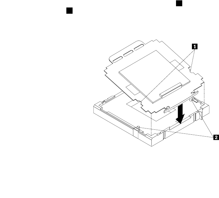
3. Note the orientation of the socket cover. Align the notches 1 of the microprocessor socket cover with
the alignment keys 2 of the microprocessor socket.
4. Install one side of the socket cover into the microprocessor socket as shown.
Figure 43. Installing the socket cover
Note: Your microprocessor socket and cover might look slightly different from the illustration.
112 ThinkCentre E93 Hardware Maintenance Manual