


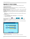

Appendix 11: Full Connectivity Diagram
74
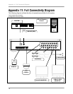
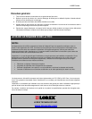
Appendix 11: Full Connectivity Diagram
The following diagram outlines the slate of connections available for the system:
*Not included with the system.
†Configuration varies by model.
ETHERNET
ALARM IN RELAY PTZ RS-232
PS/2
POWER
DC12V
CH1 CH2 CH3 CH4 CH5 CH6 CH7 CH8
CH9 CH10 CH11 CH12 CH13 CH14 CH15 CH16
AU1 AU2 AU3 AU4
CH1-4 CH5-8 CH9-12 CH13-16
AU OUT MONITOR SPOT
1 2 3 4 G 5 6 7 8 G 9 101112G 13141516G
NO NC
D+ D-G TXRX
COM
WAN 1 2 3 4 UP PWR
PC for Remote
Access*
PUBLIC VIEW
MONITOR*
ROUTER*
CAMERAS
†
SPEAKERS*
SENSOR*
MOUSE (PS/2)
PTZ
Camera*
SLAVE MONITOR*