


5-16 Lucent Technologies Inc.
USS-720
Instant USB
Preliminary Data Sheet, Rev. 5
USB-to-
IEEE
1284 Bridge September 1999
13
IEEE
1284 Port (continued)
Data Register
Status Register
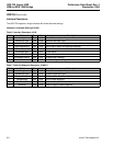
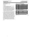
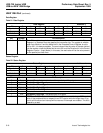
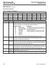
Table 21. Data Register
Data Register Address: 0
Bit 7 6 5 4 3 2 1 0
Symbol D7 D6 D5 D4 D3 D2 D1 D0
Access R/W R/W R/W R/W R/W R/W R/W R/W
Default 0 0 0 0 0 0 0 0
Bit Symbol Bit Description
7—0 D7—D0 Data. This register is equivalent to and operates in the same manner as the Data
Register in a standard host-side parallel port controller chip. The register is writable
when Auto Mode is 0 and the Mode field in the Extended Control Register is set to
000 or 001. It is always readable. The read value will be the value of the data latched
into the register unless the Mode field is set to 001 and the Direction bit in the Control
Register is set to 1 (Input Mode). In this case, the read value will be the value present
on the parallel port data lines.
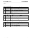
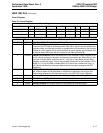
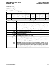
Table 22. Status Register
Status Register Address: 1
Bit 7 6 5 4 3 2 1 0
Symbol nBusy nAck PError Select nFault — PLH Timeout
Access Read Read Read Read Read Read Read Read
Default X X X X X X X 0
Bit Symbol Bit Description
7 nBusy Inverted Busy. An inverted version of the parallel port Busy signal.
6 nAck Parallel Port nAck Signal.
5 PError Parallel Port PError Signal.
4 Select Parallel Port Select Signal.
3 nFault Parallel Port nFault Signal.
2—Reserved.
1 PLH Peripheral Logic High. The parallel port PLH signal.
0 Timeout EPP Time-Out. This bit indicates that a time-out has occurred during an EPP read or
write. If the peripheral fails to respond to an EPP read or write for longer than 10 µs,
this bit will be set and an interrupt will be returned if interrupts are enabled. This bit is
cleared by a read.