Preliminary Data Sheet, Rev. 5 USS-720
Instant USB
September 1999 USB-to-
IEEE
1284 Bridge
Lucent Technologies Inc. 5-17
13
IEEE
1284 Port (continued)
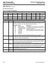
Control Register
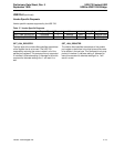
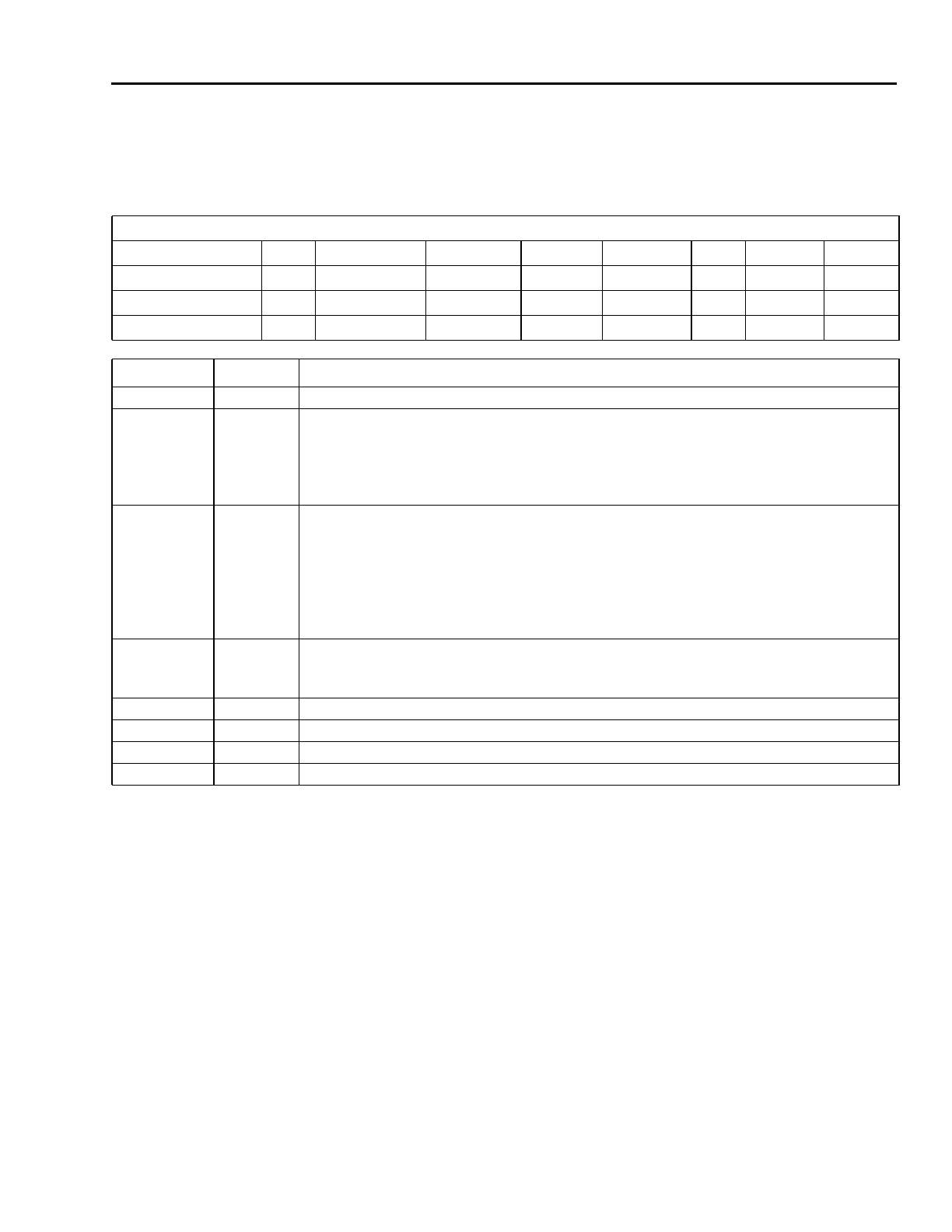
Table 23. Control Register
Control Register Address: 2
Bit 7 6 5 4 3 2 1 0
Symbol HLH EPP mask Direction Int enbl SelectIn nInit AutoFd Strobe
Access R/W R/W R/W R/W R/W R/W R/W R/W
Default 0 1 0 0 1 1 0 0
Bit Symbol Bit Description
7 HLH Host Logic High. The parallel port HLH signal.
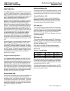
6 EPP mask EPP Time-Out Interrupt Mask. This bit masks the generation of an interrupt upon
time-out of an EPP data or address transfer. Note that in typical host-side parallel port
controller chips, this interrupt condition is grouped with and controlled by the Interrupt
Enable bit in this register; so for exact emulation of typical parallel port hardware, this
bit should always be written with the inverse of the Interrupt Enable bit.
5 Direction Parallel Port Direction. When the Mode field in the Extended Control Register is set
to 001, this bit controls the direction of the parallel port data lines. When set to 0, the
lines are in Output Mode, and when set to 1, they are in Input Mode (see the Data
Register on previous page). This bit also controls the direction of the interface in ECP
Mode (011). It has no effect in Modes 000 or 010 (which are unidirectional only), or
100 (where the direction is uniquely determined by the type of access to the EPP
Registers).
4 Int enbl Interrupt Enable. This bit enables interrupt generation on nAck events. If this bit is
set, interrupt status will be generated on transitions of nAck from low to high (this
status being reflected by the nAck Interrupt bit in the USS-720 Control Register).
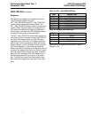
3 SelectIn Inverted nSelectIn. An inverted version of the parallel port nSelectIn signal.
2 nInit Parallel Port nInit Signal.
1 AutoFd Inverted nAutoFd. An inverted version of the parallel port nAutoFd signal.
0 Strobe Inverted nStrobe. An inverted version of the parallel port nStrobe signal.


