


13
Lucent Technologies Inc. 6-1
Application Note
February 1999
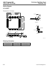
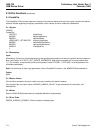
Typical Circuit Showing the USS-720
Bridging USB to Parallel Port
Description
The USS-720 can be used in a variety of applica-
tions, such as bus-powered devices, self-powered
devices, hubs, and embedded printer controllers. The
following describes using the device in a bus-
powered application (see attached schematic).
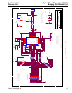
Note: The attached schematic depicts a typical func-
tional circuit using the USS-720 as a bridge
between the USB and a parallel port. Actual
applications may require additional protection
circuitry. The schematic and circuit description
provided in this application note are for refer-
ence purposes only. Neither Lucent nor In-
System Design warrants their suitability for
any particular purpose.
The USS-720 is a dual-powered chip requiring both
5 V and 3.3 V supplies. The 3.3 V is generated using
a low dropout regulator. The USS-720 must operate
with a USB supply (VBUS) of 4.4 V to 5.25 V. Using a
low dropout regulator ensures a solid 3.3 V supply
even at the lowest limits of the 5 V VBUS. The 5 V
supply is used by the 1284 printer port drivers.
The USS-720 also requires a 12 MHz ± 0.25%
crystal. In embedded applications, an oscillator
output should be connected to clk_lo (pin 21), and
pin 22 should be left unconnected.
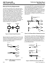
The USS-720 requires a 1.5 kΩ pull-up resistor
attached to the DPLS signal to indicate that it is a
high-speed 12 Mbits/s device as per the USB specifi-
cation. There is also a USB differential driver imped-
ance specification of 30 Ω to 42 Ω. A 24 Ω series
resistor, when added to the output impedance of the
USS-720 USB drivers, puts the total output imped-
ance in the middle of that range.
A similar driver output impedance requirement is true
for the
IEEE
* 1284 printer signals. A 24 Ω series
resistor is used on all the 1284 signals that are driven
by the USS-720 to give each signal a total output
impedance of 45 Ω to 55 Ω . The
IEEE
1284 specifi-
cation also requires 1.2 kΩ pull-up resistors on all the
printer signals, except PLH. PLH only requires a
7.5 kΩ pull-down resistor.
While the
IEEE
1284 specification requires these
resistors, developers must make their own design
decisions against the 500 µA suspend mode current
requirements of the USB specification. The following
schematic does not show the pull-down resistor on
the PLH signal. The internal pull-down on the USS-
720 can be used for this purpose. Similarly, the pull-
up resistor values may have to be modified to higher
values than the
IEEE
1284 specification allows in
order to meet the USB requirements.
Standard decoupling should be used on the board. It
is recommended that 0.1 µF capacitors are placed
between VCC_5V/VCC and GND and that they are
located as close as possible to the power pins on the
USS-720. Sufficient grounding must be implemented
on the board to ensure proper functionality. A four-
layer board design is recommended with two of the
layers used for power and ground planes.
The test and scan signals (pins 23, 24, 31, 32, and
33) are used for functional testing after fabrication
and are tied low during normal operation. It is recom-
mended that typical bypass techniques be used on
the voltage supply pins (see ASIC BYPASS CAPS on
attached schematic).
The USS-720 contains a small amount of ROM
space that is used to store descriptor data. This data
is used during the Plug and Play mode in a
Microsoft
Windows
†
operating system to identify the product.
This onboard ROM data can be used during the ini-
tial development phase, but unique descriptor data
must be provided by the USB peripheral developer
for each design.
*
IEEE
is a registered trademark of The Institute of Electrical and
Electronics Engineers, Inc.
†
Microsoft
and
Windows
are registered trademarks of Microsoft
Corporation.