


6-2 Lucent Technologies Inc.
Typical Circuit Showing the USS-720 Application Note
Bridging USB to Parallel Port February 1999
13
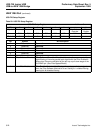
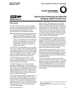
Description (continued)
Whenever device descriptor data is requested, the
USS-720 drives both control pins CS (pin 35, Serial
ROM Chip Select) and SK (pin 34, Serial ROM Clock).
The USS-720 then looks for a response on DIO
(pin 36, Serial ROM Data Signal). If there is no external
device connected, and no data is present on the DIO
pin, then the descriptor data is taken from the internal
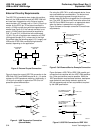
ROM. The USS-720 accesses this data through a
MicroWire
* ROM Interface. One method for this is to
use an EEPROM such as the 93CS56L/66L. The USS-
720 Evaluation Kit is specifically designed for use with
this part. Substitution components must be pin and
functional compatible with the 93CS56L/66L. 93C56L/
66L, 93CS46L, and 93C46L EEPROM parts will not
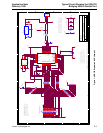
work. The connection scheme for this device is shown
on the attached schematic. The circuit diagram
assumes that a preprogrammed EEPROM is used.
Note: Developers using the USS-720 must use an
external serial EEPROM (or the equivalent) in
their design and create their own hex data file for
use in programming the EEPROM at their site.
The configuration data stored in this serial
EEPROM is used by the
Microsoft
host software
during the enumeration to load the appropriate
drivers. Using unique identification data in the
EEPROM provides a means for the developer to
ensure that only their software is loaded for use
with their device. Otherwise, the enumeration of
a camera using the USS-720 could cause the
software for a USS-720-based printer to be
loaded, resulting in a system that does not func-
tion correctly.
See the Device Descriptor, Configurations, and
Interfaces section in
USS-720 USB-to-
IEEE
1284 Bridge
Data Sheet for more information on
device descriptors.
*
MicroWire
is a registered trademark of Advanced Interconnection
Technology, Inc.