


Preliminary Data Sheet, Rev. 5 USS-720
Instant USB
September 1999 USB-to-
IEEE
1284 Bridge
Lucent Technologies Inc. 5-25
Filter Bypass Mode
For embedded applications, the USS-720
IEEE
1284
port can be operated in Filter Bypass Mode. This mode
disables digital filtering of the parallel port signals into
the USS-720, providing a performance improvement.
Note: Since digital filtering is disabled, the parallel port
lines will be susceptible to noise. Do not use this
mode when driving across a cable.
Filter Bypass Mode is enabled by connecting a 20 kΩ
pull-down resistor to the SUSPEND line.
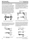
High Drive Mode
If desired (e.g., for embedded applications), the USS-
720
IEEE
1284 port can operate in High Drive Mode. In
this mode, all parallel port signals are constantly driven
by 14 mA totem-pole drivers, rather than with the
normal open-drain drivers. This eliminates the need for
external pull-up resistors on the parallel port signals
(and, if driving another chip on the same board, there
is no need for the 24 Ω impedance matching resistors).
High Drive Mode is enabled by connecting a 20 kΩ
pull-down resistor to the SK line.
Self-Powered Mode
When using the USS-720 in a self-powered applica-
tion, attach a 5 kΩ pull-up resistor to the CS line. This
causes the correct self-powered status to be reported
in response to a USB Get-Status command.
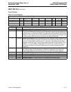
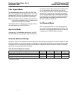
Absolute Maximum Ratings
Stresses in excess of the absolute maximum ratings can cause permanent damage to the device. These are abso-
lute stress ratings only. Functional operation of the device is not implied at these or any other conditions in excess
of those given in the operations sections of this data sheet. Exposure to absolute maximum ratings for extended
periods can adversely affect device reliability.
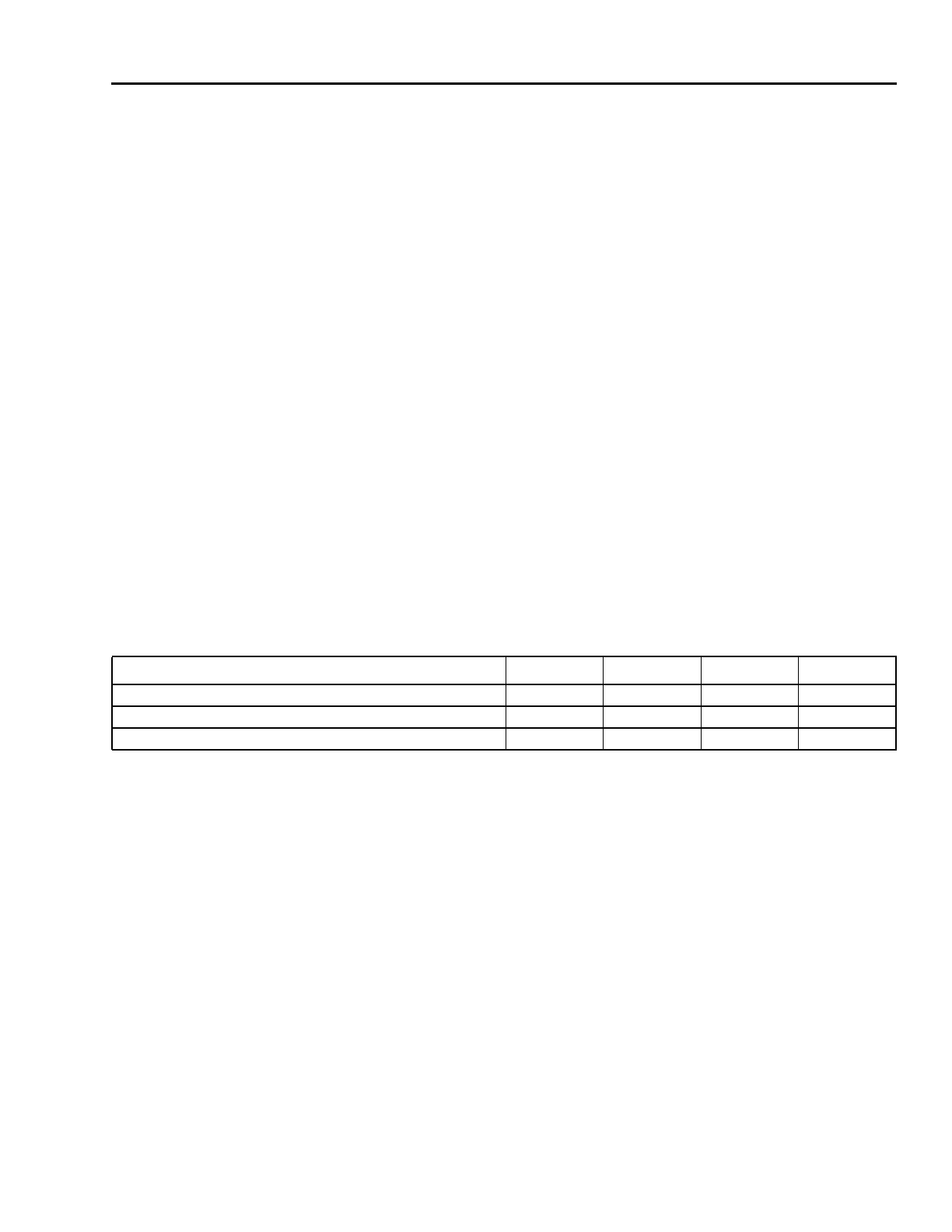
Table 30. Absolute Maximum Ratings
Parameter Symbol Min Max Unit
Ambient Operating Temperature Range TA 070°C
Storage Temperature Tstg −40 125 °C
Voltage on Any Pin with Respect to Ground VIN VSS − 0.3 VDD + 0.3*
* Except for 5 V tolerant buffers where VIN max = VDD5 max + 0.3 V. VIN must never exceed VDD5 + 0.3 V at any time. VDD5 should be selected
to satisfy this condition.
V